I also tried to simulate a different cross point, 2800hz LR4.
I don't know if it could be good for the beaming of the 18W, also phase tracking can be improved.
1.7khz LR4 is spectacular, but with 2.8khz it "seems" there is a "natural" notch in the range of 200-1000hz. who knows.
The 18W8531 does a large SPL step on axis starting at 900Hz. That means also beaming starts probably very heavy with this driver at that point. Maybe a higher X-over is better then, because dispersion transition from woofer to tweeter is better. But these are things that have to be measured.
But you can give it a try, when it sounds good you have to do it. Also SF does it in that way. They are not stupid 🙂.
I completely agree, our experiences are the same 🙂
Right now, i think your filter 18 is an improvement of the 17th, if we decide to cross a 1.7khz.
Have you seen my sim of the 2.8khz cross point? maybe is too high, maybe 2khz is better . I do this because I would like the 18w sounds as high as possible, but I know the beaming problem.
would you try to simulate something like 2khz -2.8khz crossing point LR4 and evaluating phase and off axis response? with filter 17 phase is perfect, not also with mine 2.8khz sim.
I also like symmetrical cap value on tweeter like ProAc design 🙂 🙂 🙂
I will do later this day.
The problem I already saw is the 18W is missing some power above 2kHz.
I will have a look at.
Cucicu
From now on I will use also diBirama frd to create the infinite baffle models in Leap. I had a closer look on their site, it looks very good, very well documented, it gives a lot of trust indeed. A pity I haven't done that earlier, but it has happen. So we are on the same line.
It explains already the 2dB level difference for the tweeter SPL ... damned 🙂
Cucicu
I have simulated again filter17 based now on dibirama infinite baffle responses.
I have created new Leap infinite baffle models based on dibirama.
To create the woofer in enclosure frd I have used Bagby diffraction calculator.
For the tweeter in enclosure frd I have used the Leap diffraction calculator. For the tweeter baffle response Leap and Bagby map perfectly on each other.
These are the results now for filter 17.
Schematic filter 17 with resistor R6 added

SPL filter 17 with resistor R6 added @ diBirama frd

Phase filter 17 with resistor R6 added @ diBirama frd

Woofer is 20 mm behind tweeter in this simulation.
Woofer response looks good. Technically the tweeter response can be better IMO. I will try to improve. If it will sound better then??
Forget filter 18 of yesterday. I will look also to your last LR4 posts.
I have simulated again filter17 based now on dibirama infinite baffle responses.
I have created new Leap infinite baffle models based on dibirama.
To create the woofer in enclosure frd I have used Bagby diffraction calculator.
For the tweeter in enclosure frd I have used the Leap diffraction calculator. For the tweeter baffle response Leap and Bagby map perfectly on each other.
These are the results now for filter 17.
Schematic filter 17 with resistor R6 added
SPL filter 17 with resistor R6 added @ diBirama frd
Phase filter 17 with resistor R6 added @ diBirama frd
Woofer is 20 mm behind tweeter in this simulation.
Woofer response looks good. Technically the tweeter response can be better IMO. I will try to improve. If it will sound better then??
Forget filter 18 of yesterday. I will look also to your last LR4 posts.
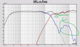
Paul, I don't deny you best intentions here. You try to help.
But how can you, along with your target curves of LR2, BW3 and LR4, ignore the elephant in the room? 😀
TBH, a 4th order crossover would make more sense. 😎
Hi Steve,
There are two reasons why that elephant is still ignored for the moment.
1. I have tried to keep it simple, because I know Cucicu has not many components in home at this moment. And doing like this, we already maked some progress IMO.
2. I already saw that mapping the woofer perfect on LR4 target will create a too much phase lag in the woofer system with a bad sum response as a consequence. But probably a better compromise is possible.
I also should start with a more accurate design, but its Cucicu's project and I take that into account. I am working at a new LR4 proposal with extra attention to the tweeter off axis response and to design on target in the best way.
This is the tweeter off axis response to show that only optimizing tweeter response on axis is not good.
Cucicu, how is the set up of your stereo speaker set.
In the left speaker, is the tweeter at the left side of the front baffle?
In most cases I optimize the 15 degree response.
SPL tweeter in enclosure 0 15 30 45 60 degrees horizontal

Cucicu, how is the set up of your stereo speaker set.
In the left speaker, is the tweeter at the left side of the front baffle?
In most cases I optimize the 15 degree response.
SPL tweeter in enclosure 0 15 30 45 60 degrees horizontal
Regarding the woofer, I can say it sounds and looks better at sim with 3rd order filter 2.2mh/6.8ohm-1R/0.20mh.
Maybe we should go for a B3 arrangement trying to make the phase better. It s my opinion because this way we dont have any elephant in the room
Maybe we should go for a B3 arrangement trying to make the phase better. It s my opinion because this way we dont have any elephant in the room
This is the best LR4 I can make at this moment.
Looking both to 0degree and 15 degree SPL responses and phase aligning. And making the schematic not too complex.
It is not the best enclosure to make a good on and off axis response.
Schematic filter19 LR4 1700

SPL 0 degree filter19 LR4 1700

SPL 15 degree H filter19 LR4 1700

Phase filter19 LR4 1700

Looking both to 0degree and 15 degree SPL responses and phase aligning. And making the schematic not too complex.
It is not the best enclosure to make a good on and off axis response.
Schematic filter19 LR4 1700
SPL 0 degree filter19 LR4 1700
SPL 15 degree H filter19 LR4 1700
Phase filter19 LR4 1700
Paul, I didn`t see the polarity was reversed at the speaker units, only looked at the source, sorry. The dbirama files do create a very flat response in my XSim.
Do a 2.8Khz and you`d get the Klingon Bird of Prey dispersion characteristic (sonogram). Very undesirable 🙂
Do a 2.8Khz and you`d get the Klingon Bird of Prey dispersion characteristic (sonogram). Very undesirable 🙂
Is there a 0.33uf in series with the woofer?
A coil of 0.33mH/0.3Ohm yes. The combination of that coil with the increase of capacitor C15 to 20uF realizes a better map on target for the woofer.
It can be critical, I know, but it better reduces the break up region of the woofer. Maybe try and listen.
Last edited:
No paul. It is not good.
I give up.
It's a pity. From my side I only can give you some reference designs here on the forum and hope that the response is matching with the drivers you actually have.
You should be able to create at first a reference design based on measurements and then tweak it with listening and simulation. You should work in that direction. Trial and error can become very frustrating.
Maybe it is not that good midwoofer to realize the result you are looking for. Also Troels was not so happy with that driver.
Least but not last i am try to simulating series crossover.
At first attempt it looks very good, slopes are smoother than parallel crossover and cross and phase are much better. Whatbdo you think paul?
At first attempt it looks very good, slopes are smoother than parallel crossover and cross and phase are much better. Whatbdo you think paul?
Cucicu
I have the B3 1700Hz with the dibirama targets. Difficult to make a good design on and off axis. It is what it is.
Schematic filter20 B3 1700Hz

SPL 0 deg filter20 B3 1700Hz

SPL 15 deg H filter20 B3 1700Hz

I have the B3 1700Hz with the dibirama targets. Difficult to make a good design on and off axis. It is what it is.
Schematic filter20 B3 1700Hz
SPL 0 deg filter20 B3 1700Hz
SPL 15 deg H filter20 B3 1700Hz
Least but not last i am try to simulating series crossover.
At first attempt it looks very good, slopes are smoother than parallel crossover and cross and phase are much better. Whatbdo you think paul?
First order serial ?
- Home
- Loudspeakers
- Multi-Way
- Scan-Speak crossover help