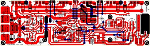
but it is real close, baker clamps were not incorporated,
but the jumper options for the cascode is there.....
but the jumper options for the cascode is there.....
If I could see the layout for V2.4 I could probably adjust it. Where can I see that?
Last edited:

Almost certainly someone created the files prior to manufacturing the boards that were available in the store. That guy might still have these files?
Best regards!
Best regards!
I found it.
I can't open the file Badger_V2. silk.pdf. Is the file broken? Also, I believe the traces for the other side of the PCB are missing.
Wouldn't it be better to have the full (pre-PDF) files available so we could send these out to a manufacturer and get finished boards with drilled holes and all?
My thoughts also!
This were consistent with a claim that I've read elsewhere in this forum: Every company should make all their service manuals public domain if it is about getting out of business.
Best regards!
This were consistent with a claim that I've read elsewhere in this forum: Every company should make all their service manuals public domain if it is about getting out of business.
Best regards!
there is a complete documentation about this amp here written by JojoD, just search for it...
also, i have inquired from Variac if there are plans to replenish stock boards,
while diy board is so much fun, i would like to have professionally made boards...
also, i have inquired from Variac if there are plans to replenish stock boards,
while diy board is so much fun, i would like to have professionally made boards...
I got the sprint file from here. When I get to my computer I will attach the file. I made the pdfs because that is what AJT asked for.
draw out your LTP+source resistors, with the two voltages @ +IN & -IN.
Measure the Vgs of both halves.
Mark that on your sketch.
Measure the Vdrop across each Source resistor.
Mark that on your sketch.
Does that all add up?
BTW,
The k170 datasheet shows ~180mVgs for a 6.2mA Idss device operating @ 2mA.
What should your Vgs be for your devices at your currents?
Built the second board.... this time is even worst, offset near 0.7V and heavy oscilation (11VAC at 400khz)
Tryed changing the drivers but did not cure it.
I am really sad about this
Interestingly it does oscilate even if I disconnect the output devices so oscilation is on the driver stage.... will try to increase base stoppers
Why don't you start with the standard Honey Badger design (which is known to work well), and then start modifying this towards your liking? This might make it easier to understand where/why you get oscillation and DC offset.Interestingly it does oscilate even if I disconnect the output devices so oscilation is on the driver stage.... will try to increase base stoppers
Built the second board.... this time is even worst, offset near 0.7V and heavy oscilation (11VAC at 400khz)
Tryed changing the drivers but did not cure it.
I am really sad about this
did you try adjusting tail currents?
did you try adjusting tail currents?
Yes, increasing big ccs current slightly reduces offset but only slightly, from .3 to .25v
- Home
- Amplifiers
- Solid State
- diyAB Amp - The "Honey Badger"