A big thanks to all the recent posters for their time and efforts - and sharing their MFB knowledge. With all the suggestions, information and step by step, particularly from Gnobuddy, Stephen, bolserst, KSTR and Bentoronto I have some additional ideas on how to proceed - the dream of:
Plug and Play Pocket Piezo(TM) to servo-bass bliss (leading of course to world domination) is on its way to becoming reality.
Here is what I know:
1. The circuit in the Genesis piezo based system uses just three op amp stages: from piezo to 1. a buffering / difference amp (all four 220k ohm resistors) to 2. An integrator with gain, to 3. a mixer / difference amp + integrator/filter. And it works with 2 opposing 12" woofers crammed in ~ 1.6 ft3 box down to 16Hz. Based on the one pic I have seen of the piezo in a Genesis woofer, it may be smaller than the one I am using, but I do have piezos with other diameters and thickness to try if needed.
2. The Sony circuit seems to have the essence of this circuit, sans the integrator, but I think buffering op amp (IC201 2/2) could be turned into the integrator - however bolserst advices to NOT do this (if you could elaborate why not, I would appreciate it)
3. The piezo output direct into the scope looks very good - I can imagine how one could spend a lot of time tweaking the mounting / seismic mass and more to get significantly different outputs and mechanically changes its resonance.
Big Picture / Goals
Get the piezo to work with the Sony amp and woofer.
Buy a better woofer - see if piezo will work with it; if it does,
Get a better amp, suture piezo-based op amp MFB circuit into better amp, use with better woofer thus creating a mellifluous chimera.
Next obstacle to surmount - the phase of the piezo output...As Steph_tsf alluded to, maybe instead of measuring output across MFB 0.22 Ohm resistor I should look at signal at the non-inverting terminal of op amp (IC202 2/2) and compare this to the piezo output instead. Next report Friday night.
You mention an integrator with gain before the mixer. Did you verify the value of the feedback capacitor? It is most likely just a LP filter to roll off response above 1kHz, not an integrator. Have you measured the capacitance of the Genesis piezo? If your circuit tracing is correct and the input impedance is 440K then I would wager their piezo has much higher capacitance than the one your are using.…The circuit in the Genesis piezo based system uses just three op amp stages: from piezo to 1. a buffering / difference amp (all four 220k ohm resistors) to 2. An integrator with gain, to 3. a mixer / difference amp + integrator/filter….the piezo in a Genesis woofer, it may be smaller than the one I am using, but I do have piezos with other diameters and thickness to try if needed.
Post#540
Post#542
As mentioned previously, if you are using a sensor that provides output proportional to acceleration, and you put an integrator in the feedback loop BEFORE the mixer, you will get a response that has a 6dB/oct slope rather than the desired flat response.The Sony circuit seems to have the essence of this circuit, sans the integrator, but I think buffering op amp (IC201 2/2) could be turned into the integrator - however bolserst advices to NOT do this (if you could elaborate why not, I would appreciate it)
You might review Attachment#8 from Post#464
I would again recommend to stop wasting time trying to compare piezo and sense resistor outputs from the Sony close loop system. The first step is to understand what your piezo sensor + buffer circuit is actually giving you. To do this you need to put the woofer in a close box of known volume(free air is also an option) and feed it a frequency independent sweep so you can measure the magnitude and phase response from 10 Hz to 5kHz of the output of the sensor buffer. Basically, you need to determine the open loop response of your woofer/sensor system as shown in Attachment#1 of Post#464Next obstacle to surmount - the phase of the piezo output...As Steph_tsf alluded to, maybe instead of measuring output across MFB 0.22 Ohm resistor I should look at signal at the non-inverting terminal of op amp (IC202 2/2) and compare this to the piezo output instead.
As Gnobody mentioned, once you’ve done this step, we can help you:
1) determine if you buffer circuit needs to be modified for improved LF response
2) define changes to the Sony circuit neccessary to achieve a stable MFB ciruit.
Indeed. LTspice is a great tool, able to tell GO or NOGO about any possible idea and implementation. Unfortunately, hombre appears to reject such opportunity. As consequence, he doesn't realize yet and he can't understand yet a few evidences.I would again recommend to stop wasting time trying to compare piezo and sense resistor outputs from the Sony closed loop system.
What you call "an integrator with gain" is an equalizer, boosting the low frequencies. Such boost is required for compensating the 1st-order highpass filter formed by the 440 kilo ohm impedance that's loading the 38 nF piezo sensor capacitance.Here is what I know: The circuit in the Genesis piezo based system uses just three op amp stages: from piezo to 1. a buffering / difference amp (all four 220k ohm resistors) to 2. An integrator with gain, to 3. a mixer / difference amp + integrator/filter.
Attachments
Maybe time to move ahead by assessing the phase and thus establishing how feasible it would be to proceed without worrying about destroying a driver in an instant of Nyquist revenge.Thank you.
What would I compare the phase to in this sweep you suggested - the input signal?
In ancient times, 'scope-hackers kept a transparent plastic screen overlay in their accessory drawer that was marked for phase when doing an XY plot.
You want to compare the feedback signal to whatever is happenin' at the point it connects back to.
Ben
Yes. What you need, to be able to proceed with confidence, is the mathematical connection between the voltage driving the woofer, and the signal coming back out of the piezo. Without any of the existing Sony filters, integrators, summers, differencers, phase-shifters, ports, or watchemacallits involved. 😀 Just the bare woofer (no box), or woofer in a sealed box of about the eventual volume you're planning to use.Thank you.
What would I compare the phase to in this sweep you suggested - the input signal?
Most decent sweep measurement systems can use a loop-back measurement - you connect signal out directly to signal in, tell the software it's a loopback test, and run a sweep. The software then takes that as a baseline, and uses it to figure out any unwanted phase or amplitude shifts in the test equipment itself.
Then, you disconnect the loop-back, and instead drive the woofer from the sweep signal out (meaning you need a power amp between software and speaker, of course). The piezo - along with any buffer you're using, but no additional filtering - feeds back to the sweep signal input.
You should end up with the frequency and phase responses of your woofer/piezo system. That's the starting point for building an MFB system.
Work is keeping me very busy, but if I get a little free time, I'll try to continue to contribute what I can here.
-Gnobuddy
Considering motion-/acceleration sensors, please also take in account the microphonic properties of the device. One of the reasons the former Philips MFB's used a rubber-suspended device. The other reason was to dampen the low-rise characteristic of the output, as far as I understood.
(Yes, the "solder-blob" acts as a mechanical amplifier for the output-signal.)
The loudspeakers do not perform in a disturbance-free environment, so the microphonics can cause problems.
Also problematic might be the sub-sonic wobble of the conus that might occur when the sensor is placed incorrectly.
All good points: but is any sensor method less susceptible to these artefacts? Acceleration because its output as a mic drops off with lower frequencies?Considering motion-/acceleration sensors, please also take in account the microphonic properties of the device.
The loudspeakers do not perform in a disturbance-free environment, so the microphonics can cause problems.
Also problematic might be the sub-sonic wobble of the conus that might occur when the sensor is placed incorrectly.
BTW, it has always seemed to me that a MF sub in the corner of the room acts as an active sound absorber, although the configuration is unlikely to eat too much sound.
B.
I'm attaching two commented schematics and simulations. I am in search of somebody willing to confront this to the real world. A difficulty is to firmly hook the 15 mm piezo disc without obstructing the pole piece ventilation, and without reducing the Xmax.
Attachments
-
Closed Box MFB (standard 4 ohm woofer).asc11.4 KB · Views: 87
-
 Closed Box MFB (standard 4 ohm woofer) (schema).png107.8 KB · Views: 214
 -
 Closed Box MFB (standard 4 ohm woofer) (curves).png28.2 KB · Views: 238
 -
Closed Box MFB Genesis (standard 4 ohm woofer).asc13.5 KB · Views: 77
-
 Closed Box MFB Genesis (standard 4 ohm woofer) (schema).png111.8 KB · Views: 215
 -
 Closed Box MFB Genesis (standard 4 ohm woofer) (curves).png28.3 KB · Views: 117
I guess no sensor method will be ideal. I expect all sensor systems to have their specific problems and limitations. Task of the designer is to reduce them to a level that's acceptable and enables the design objectives (better bass-response and lower distortion) to be reached under all operating conditions.All good points: but is any sensor method less susceptible to these artefacts? Acceleration because its output as a mic drops off with lower frequencies?
BTW, it has always seemed to me that a MF sub in the corner of the room acts as an active sound absorber, although the configuration is unlikely to eat too much sound.
B.
Sorry, cannot comment on the properties of a corner-placed MF sub-woofer. Never tried that.
Are you familiar with MfbLabs ? It's a Dutch site dedicated to MFB. You could also try to discuss your ideas on that site.I'm attaching two commented schematics and simulations. I am in search of somebody willing to confront this to the real world. A difficulty is to firmly hook the 15 mm piezo disc without obstructing the pole piece ventilation, and without reducing the Xmax.
You mention an integrator with gain before the mixer. Did you verify the value of the feedback capacitor?
Yes, the capacitance value shown in my circuit is correct. I am going to try to upload a link to a circuit later with more details.
It is most likely just a LP filter to roll off response above 1kHz, not an integrator. Have you measured the capacitance of the Genesis piezo? If your circuit tracing is correct and the input impedance is 440K then I would wager their piezo has much higher capacitance than the one your are using.
Please see attached photo - I measured the capacitance of a few different piezos, and the one in my Genesis speakers. I must invoke not the Heisenberg's uncertainty principle but something closely related- the observer effect - I am guessing the capacitance values are off a bit due to the process of measuring it (and hearing a buzz while measuring), so values below are approximations.
Left to right -
1. Ceramic 15/25mm on both sides of the disc, and thick (i think these were $15 each); 2nF [mfg. rating: Static capacitance Cs: 1900pF±15%@ 1kHz]
2. 17mm diameter ceramic (cheapo); 24 nF
3. 24mm diameter ceramic (cheapo); 32 nF
4. 22mm diameter thicker ceramic ($8 each); measured 48 nF [ mfg. ratings: Static capacitance Cs: 54nF±15%@1kHz]
5. Genesis measured but not seen, louder sound than all the others when measuring - 77nF.
Bolserst, I am duly impressed with your prediction of the Genesis piezo capacitance being much higher than the one I was using (18nf) - the capacitance of the piezo in the Genesis speaker is 77nF - round of applause for bolserst.

So, this makes me wonder about the size / type of piezo inside the Genesis - how to deduce based on these values and this picture? This diameter looks smaller than 25mm compared to voice coil....unless their woofers have large voice coil (doubt it). Greater thickness? Not legitimate pic or a woofer piezo that has been repaired?

Last edited:
Those are my thoughts also. Considering the rather long wavelengths of the frequencies where MFB is most active (3.4 metres at 100 Hz, for example), it isn't going to produce much cancellation. At worst, perhaps, a tiny bass-only "cone of silence" right next to the driver....it has always seemed to me that a MF sub in the corner of the room acts as an active sound absorber, although the configuration is unlikely to eat too much sound.
I remember listening for this when I built my first MFB prototype. I never heard anything, though!
(For those who don't recognize it, "cone of silence" is a reference to a recurring joke in an idiotic American comedy series about an incompetent secret agent named Maxwell Smart. The cone of silence is a device supposed to produce a small, silent, sound-isolated, region for the safe discussion of top-secret material, but it never actually works as intended.)
Subwoofers may not work to provide sound cancellation, but there were a few generations of Maxell sound-cancelling headphones that used this exact idea, with a tiny electret microphone that sensed the ambient acoustic signal at your ears, and attempted to use the headphone diaphragm to cancel it.
Those headphones were not spectacular at noise reduction, producing just a few decibels of noise reduction at best. But, IMO, they were spectacular for bass quality and extension, particularly since they were of a small, light, supra-aural design.
Maxell never advertised the improved bass performance, only the sound-cancellation aspect of it. I'm sure I'm not the only person who noticed the improved bass, but I never saw anything about it on the Internet, either.
Back to the MFB-sensor-as-microphone issue, a subwoofer is a horrible microphone, anyway; good microphones have the lightest wisp of a diaphragm that can be engineered - often only 3 microns thick, with just micrograms of total moving mass.
By contrast, subwoofers have at least tens of grams of moving mass. So we can expect them to be tens or hundreds of thousands of times - maybe even millions of times - less sensitive at picking up sounds.
-Gnobuddy
Considering motion-/acceleration sensors, please also take in account the microphonic properties of the device. One of the reasons the former Philips MFB's used a rubber-suspended device. The other reason was to dampen the low-rise characteristic of the output, as far as I understood.
(Yes, the "solder-blob" acts as a mechanical amplifier for the output-signal.)
The loudspeakers do not perform in a disturbance-free environment, so the microphonics can cause problems.
Also problematic might be the sub-sonic wobble of the conus that might occur when the sensor is placed incorrectly.
Disturbances by the environment are treated as errors by the feedback, just as those due to the non-linearity of the driver. It is not a default to have sensors which are sensible to them. Of course, on huge disturbances (as the driver in an accelerating car), the effect of the feedback correction has to be limited to avoid unreasonable amplitudes of the cone.
Last edited:
Originally Posted by Gnobuddy
Not at all, I absolutely don't think it's utterly ridiculous. I think it's an excellent hypothesis - an untested idea, but a perfectly good one.
But IMHO it's still worth testing, or at least simulating - firstly as a learning tool, and secondly because it's always possible you're visualizing something new and different, and it will actually work.
OK, well that's different to what you "seemed" to be implying in your post ! Thanx for the clarifications 🙂
No probs about the gender then 😉
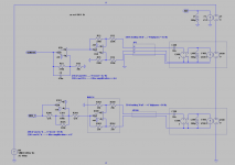
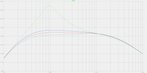
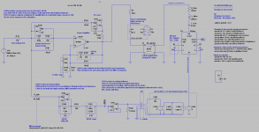
Please tell me your opinion about the attached circuit. The DC-servo is there for stabilizing two amplifiers in series. Hooking the DC-servo this unconventional way solves a major MFB instability issue in the subsonic domain.
Please notice the mixer and the power amplifier, exhibiting plain normal amplification coefficients above 1 kHz. This ensures stability in the high frequencies.
Please notice the power amplifier having no local feedback in the bass frequencies. This maximizes the open-loop gain in the bass frequencies, where the MFB is dominant.
Please notice the mixer providing a progressive bass boost below 160 Hz, ending up with a x100 amplification at 16 Hz. This again maximizes the open-loop gain in the bass frequencies, where the MFB is dominant.
The MFB is dominant below 482 Hz.
There is at least 18 dB of motional feedback from 20 Hz to 145 Hz.
The motional feedback culminates at 24 dB at 90 Hz.
The motional feedback is only 3 dB at 482 Hz, at which point it blends equally with the conventional voltage feedback.
The conventional voltage feedback gets dominant past 482 Hz.
The resulting system frequency response extends from 7 Hz to 3000 Hz.
Such system frequency response fits into a 2 dB corridor.
Make sure the MFB signal has the correct polarity.
Attachments
Hi Zero D, they say about 70% of spoken communication is actually not in the words at all, but rather in body language, facial expressions, tone of voice, et cetera.OK, well that's different to what you "seemed" to be implying in your post ! Thanx for the clarifications 🙂
If we had been talking face to face, you would have had no trouble knowing what I meant. But, since all you had was just my words, it wasn't hard to misunderstand them.
It probably doesn't help that there are a few crusty diyAudio members who can be, shall we say, a little condescending in the tone of their posts! But from my point of view, life is too short for head games and power plays - I want no part of any of that sort of BS.
And now back to MFB subwoofers...sorry for the aside!
-Gnobuddy
Makes sense to me. I had an input coupling cap between the preamp and power amp - so no DC gain, and no DC offset to worry about.The DC-servo is there for stabilizing two amplifiers in series.
Is this instability something you've encountered in practice?Hooking the DC-servo this unconventional way solves a major MFB instability issue in the subsonic domain.
Please notice the power amplifier having no local feedback in the bass frequencies. This maximizes the open-loop gain in the bass frequencies, where the MFB is dominant.
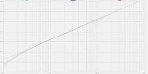
Looks like your loop gain is maximum around 90 Hz . I'm assuming the green line is the open-loop speaker response?Please notice the mixer providing a progressive bass boost below 160 Hz, ending up with a x100 amplification at 16 Hz. This again maximizes the open-loop gain in the bass frequencies, where the MFB is dominant.
This is purely a simulated woofer response, right? Because I see no cone breakup modes, and no sensor resonances, all the way out to 5 kHz.
I only worked with one woofer (an in-house, custom-made one). But that one had a huge spike in the transfer function at 1 kHz, and then several more before you got to 5 kHz.
The heartbreaking part is when you measure in-room response a metre or two away from the woofer, and your lovely +/- 1 dB near-field acoustic curve suddenly develops nasty peaks and dips from room acoustic modes! 😀Such system frequency response fits into a 2 dB corridor.
-Gnobuddy
Hi, thanks for your suggestions. Indeed the green line is the open-loop speaker response. Please note, I committed a nasty phasing error in the global DC-servo. The system can't work in real world. What warned me, was the LTspice .tran simulation, constantly outputting Giga volts.Looks like your loop gain is maximum around 90 Hz . I'm assuming the green line is the open-loop speaker response?
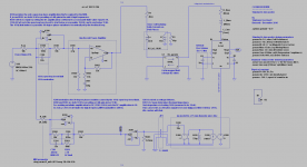
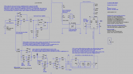
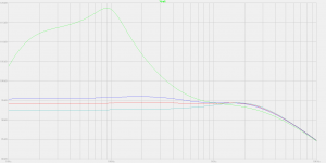
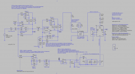
Today I have reconsidered the DC-servo arrangement, reverting back to a more conservative "one DC-servo per amplifier" scheme. See the attached files. After carefully tweaking both DC-servo blocks, the LTspice .ac simulation delivers the same outstanding frequency response curve as yesterday. I'm full aware this is only simulation. Like you wrote, I'm not expecting it to deliver such outstanding linearity once in the real world. Anyway, this looks highly encouraging.
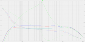
As previously explained, the frequency response curve looks outstanding.
From 7 Hz to 2000 Hz, it fits inside a 2 dB corridor.
Now pay attention to the phase curve.
The phase corresponds to a plain normal 2nd-order highpass inverter, showing a 180 degree phase in the medium frequencies.
Below 20 Hz, the phase progressively goes up by 180 degrees towards the very low frequency, just as expected from a 2nd-order highpass.
Above 1 kHz, the phase progressively goes down by 90 degree towards the high frequencies, just as as expected from a 1st-order lowpass.
This looks ideal indeed.
This time, I managed to successfully run a few LTspice .tran simulations.
They behave nicely. There are no convergence issues, and no Giga volts showing. This is another encouraging sign.
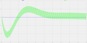
I checked the settling time at power-on, graphing what's happening when the system comes alive while receiving a small audio signal at the input.
I plotted the Mixer output voltage, and the Power Amp output voltage.
The settling is slow (in the order of one second), and this is normal, coming from a electro-acoustic system exhibiting such low frequency extension. There is nothing to worry. There is no DC saturation, no high frequency oscillation.
I also plotted the DC voltages at the outputs of the two opamps doing the DC-servo. They stay withing the power supply limits, even when considering a Mixer opamp and a Power Amp exhibiting DC offsets as high as 15 mV (input referred).
Most modern audio opamps exhibit less than 2 mV as offset (input referred).
You need FET-input opamps, as in this present schematic, they get surrounded by high value resistances, especially the opamps doing the DC-servo (1 meg), the opamp serving as Mixer (4.7 meg), and the opamp that's buffering the piezo sensor voltage (2.2 meg).
The Power Amp may feature a bipolar transistors input stage, as in this present schematic, the DC impedance around the Power Amp inputs is quite low. We have 470 ohm at the inverting input, and possibly also 470 ohm at the non-inverting input in case one adds a 470 ohm resistor in series with the Mixer output. It is thus low impedance, and possibly balanced.
Therefore, one may try a LM3886 as power amplifier, provided the chip exhibits an offset that's less than 15 mV (input referred). The NS datasheet says 10 mV max, with a DC polarization current that's 1 µA max. Looks good indeed.
Attachments
Last edited:
- Home
- Loudspeakers
- Subwoofers
- Commercial motional feedback woofer available sort of