PSU Connections
Thanks pchw, that sounds encouraging - now I need to find place on in he cd player! Could I use smaller caps that 10000uf 50v?
I have a couple of these boards unpopulated. The so called CF snubber is just a RC network (1R in series of 0.1uF) across each filter cap of each rail. Not sure it is wrong location or not, but definitely not the location that I usually associate to snubber.
NYV, yes, you can use this PSU. Just connect V+ <-> PG+ to the +ve SR, and V- <-> PG- to the -ve SR.
Thanks pchw, that sounds encouraging - now I need to find place on in he cd player! Could I use smaller caps that 10000uf 50v?
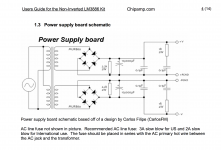
Here is the schematic.Unfortunately the powersupply came as it is - fully assembled but without any information or schematics.
It is also included in PA's enhanced schematic.
Attachments
Wrong design??
Is the design wrong for super regulator application?
In fact, the design is wrong also. Link here for more info.
Is the design wrong for super regulator application?
Thanks pchw, I planned to connect to the the power supply to the cd67 pcb through the on board 2A fuse so it powers up when the cd player is turned on.
I would think 10000 uF is good enough for a CD player especially there is a SR after that.
Also, you can use lower voltage rating cap as well. Your choice maybe determined by how much space you can fit everything inside the player!!
Also, you can use lower voltage rating cap as well. Your choice maybe determined by how much space you can fit everything inside the player!!
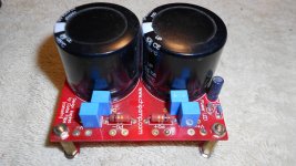
I have tested the unregulated Chipamp PS unit as is using a 50va, 15v-0-15v 3.3A torroidal transformer and dvm shows a steady +23.16v on the positive output and -23.16v on the negative output.
That's the version that has the lower rectifier bridge drawn reversed.Here is the schematic.
It is also included in PA's enhanced schematic.
The snubber is in the wrong place.
It should be before the rectifier.
The 0u1F may cause ringing rather than removing it.
The snubber is in the wrong location.
The ringing when a step change happens is between the inductance of the transformer winding and the rectifier diode when it switches off leaving the diode capacitance to ring in that LC combination. It's that LC ringing that requires damping. That is where the snubber should be.
The ringing when a step change happens is between the inductance of the transformer winding and the rectifier diode when it switches off leaving the diode capacitance to ring in that LC combination. It's that LC ringing that requires damping. That is where the snubber should be.
Ok.
So is this ps suitable for the SR or not? If not, can the snubber be 'moved' with some modifications?
So is this ps suitable for the SR or not? If not, can the snubber be 'moved' with some modifications?
Thanks for the direction AndrewT, now I am tempted to put my SR project aside and build a Quasimodo. It will also redirect me to pulling out my oscilloscopes and dusting them off. For now, I will have to figure a way of relocating the filter components - there are some excellent diagrams in the Quasimodo thread that illustrates filter locations before rectifiers. I am considering moving the offending parts to the appropriate location to under the pcb.
Next objective is finding a Quasimodo board V4! 🙂.
For now I will concentrate on using the existing components. Will keep you posted.
Next objective is finding a Quasimodo board V4! 🙂.
For now I will concentrate on using the existing components. Will keep you posted.
Snubbers
AndrewT, I found the snubber options on the Quasimodo thread.
I see this is a great learning opportunity. I would like to connect the transformer to the powersupply and see what comes up on my oscilloscope.
Then move the snubbers and repeat the test ........
AndrewT, I found the snubber options on the Quasimodo thread.
I see this is a great learning opportunity. I would like to connect the transformer to the powersupply and see what comes up on my oscilloscope.
Then move the snubbers and repeat the test ........
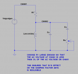
If you've already got a signal generator and two channel oscilloscope, you can use the "ExtraLight" test procedure without building a Quasomodo (or CheapoModo) printed circuit board. It's described in post #561 here. The basic idea is shown in the figure below.
Series resistor R1 works with the square wave generator to inject a current step into the transformer secondary + snubber. This very large dI/dt stimulates the RLC resonant circuit into oscillatory ringing, which you can damp by twirling the knob of 20-turn trimmer potentiometer Rs. The whole arrangement uses test equipment you already have on your bench, today, without requiring you to fab a new PCB or source any new components.
_
Attachments
Thanks for the suggestion Mark, unfortunately the only signal generator I own is an iPhone app! I am just a curious hobbyist ( with no formal electronics training), exploring the wonderful world of electronics and learning why my friend's $10,000.00 hifi sounds so good!
Then applying what I learn into my cheaper audio equipment to improve the output.
The analogue scopes I have acquired along the way are an old 20 MHz generic Chinese brand and a 50mhz GOS-Instek. Both have dual channels. I have considered a signal generator but the prices are not affordable at this time.
I am fascinated by the experimentation re: the snubber circuits and Quasimodo! I take my hat off to you sir!!
If you've already got a signal generator and two channel oscilloscope, you can use the "ExtraLight" test procedure without building a Quasomodo (or CheapoModo) printed circuit board. It's described in post #561 here. The basic idea is shown in the figure below.
Series resistor R1 works with the square wave generator to inject a current step into the transformer secondary + snubber. This very large dI/dt stimulates the RLC resonant circuit into oscillatory ringing, which you can damp by twirling the knob of 20-turn trimmer potentiometer Rs. The whole arrangement uses test equipment you already have on your bench, today, without requiring you to fab a new PCB or source any new components.
_
Are there board for the Lite version available?
If so, would an iphone, using a signal generator app be good enough to use with the Lite version of Quasimodo?
What should I look for in a good used signal generator?
Are there board for the Quasimodo ExtraLite version available?
If so, would an iphone, using a signal generator app be good enough to use with the Lite version of Quasimodo?
What should I look for in a good used signal generator?
1. Not that I am aware of
2. You need frequency > 150 Hz; Amplitude > 10V into 600 ohm load. Check whether an iPhone can achieve these specs.
3. Start a new thread or piggyback onto an existing thread. Me, I bought a Gratten ATF20B new (Amazon link), and a Wavetek 395 used (documentation). Or you could spend two hours doing the circuit design of a 12V NE555 oscillator with discrete MOSFET output stage (BS250 + 2N7000), slap it together on your solderless breadboard, and implement Quasimodo ExtraLight without buying a signal generator at all. (But if you're going to build an oscillator + output driver on your protoboard you may as well build a full Quasimodo or Cheapomodo).
Last edited:
Someone near you 🙂Anyone have a Quasimodo or Cheapmodo pcb for sale
http://www.diyaudio.com/forums/powe...using-quasimodo-test-jig-101.html#post4826781
- Home
- The diyAudio Store
- Super Regulator