Thanks
Thank you pchw,
Don't know how I missed that one!
Right on my doorstep - if it was a snake it would have bitten me in the butt!!
Order for one has been submitted.
Thank you pchw,
Don't know how I missed that one!
Right on my doorstep - if it was a snake it would have bitten me in the butt!!
Order for one has been submitted.
Signal generator
What are your thoughts on these signal generators?
FY2202S 2MHz Dual Channel DDS Function Signal Generator Sine Square Wave Sweep Counter Sale - Banggood.com
or
FY3224S 24MHz Dual-channel Arbitrary Waveform DDS Function Signal Generator Sine Square Wave Sweep Counter Sale - Banggood.com
1. Not that I am aware of
2. You need frequency > 150 Hz; Amplitude > 10V into 600 ohm load. Check whether an iPhone can achieve these specs.
3. Start a new thread or piggyback onto an existing thread. Me, I bought a Gratten ATF20B new (Amazon link), and a Wavetek 395 used (documentation). Or you could spend two hours doing the circuit design of a 12V NE555 oscillator with discrete MOSFET output stage (BS250 + 2N7000), slap it together on your solderless breadboard, and implement Quasimodo ExtraLight without buying a signal generator at all. (But if you're going to build an oscillator + output driver on your protoboard you may as well build a full Quasimodo or Cheapomodo).
What are your thoughts on these signal generators?
FY2202S 2MHz Dual Channel DDS Function Signal Generator Sine Square Wave Sweep Counter Sale - Banggood.com
or
FY3224S 24MHz Dual-channel Arbitrary Waveform DDS Function Signal Generator Sine Square Wave Sweep Counter Sale - Banggood.com
Start a new thread or piggyback onto an existing thread.
http://www.diyaudio.com/forums/equipment-tools/268317-looking-good-function-generator.html
http://www.diyaudio.com/forums/equi...gnal-generator-capable-more-than-10-vp-p.html
http://www.diyaudio.com/forums/equi...r-1hz-150khz-250khz-sine-triangle-square.html
http://www.diyaudio.com/forums/equipment-tools/294715-oscilloscope-function-generator-purchase.html
http://www.diyaudio.com/forums/equipment-tools/271867-signal-generator-100kc-s-60mc-s-audio.html
Last edited:
That FY22025S is so sweet, € 60 & free shipping, I just ordered one! One can never have too many signal generators ;-)
Jan
Jan
Signal generator
I am looking at the FY3224S - Aus$97.00 or €66. (only a $10 more than the FY22025s)
Or is theFY3224S overkill?
That FY22025S is so sweet, € 60 & free shipping, I just ordered one! One can never have too many signal generators ;-)
Jan
I am looking at the FY3224S - Aus$97.00 or €66. (only a $10 more than the FY22025s)
Or is theFY3224S overkill?
What do you mean 'work'?
I have another Siglent unit to 24MHz, never used it above a MHZ, so the 2MHz is OK for me.
Jan
I have another Siglent unit to 24MHz, never used it above a MHZ, so the 2MHz is OK for me.
Jan
I have a GW instek 3MHz sig gen. I find that the step function is just a bit too slow.
It is specified as <100ns rise/fall time. That starts to corrupt 200kHz squarewaves. It has become gross @ 500kHz
It also suffers a little overshoot and that gets into the DUT to confuse what you are trying to read.
On sinewave it has a tiny blip at the top and bottom of the waveform. Again this leads to confusion on what the DUT is doing to the signal and what is in the signal fed to the DUT.
I would be tempted to try the 24MHz if I could obtain the rise/fall times and see how clean a 100kHz sinewave is (with or without the blip).
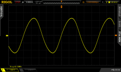
The spec document reports rise time as </=20ns.
The link to samples including sinewave from the EEVblog website -
The link to samples including sinewave from the EEVblog website -
An externally hosted image should be here but it was not working when we last tested it.
I am planning to use Super Regulator for BA3 Front End... Do you think it is worth having separate regulators/boards for 2 channels (2 positive and 2 negative regulators)?
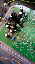
Here is my latest effort.
After doing a lot of LTSpice simulations I guess I learnt which tracks can be long and which tracks must be short, etc, to get the best out of the Jung Super Reg. I decided to build the regulator right at the load as it performs better and is more stable that way. It has a hybrid use of SMD and through-hole to lower the inductance where possible. I used only 2 layers in this 4 layer PCB for the Jung Reg. I tried to have all current loops to be the smallest, etc. I have used some opamp compensation and made provision on the PCB that I could use "remote" sensing if I want to further shorten another 3cm of tracks/plane. The remote sensing RC is shorted at the moment.
The result is good. I have just hooked it up and tested it. The output is very quiet. There is no resonance of any kind found. I guess after 4 rounds of PCB design this one might have cut it.
The heatsink was measured 40 degree temperature only. I have a 5W 150R resistor at the output to draw a constant current of 100mA in order to lower the output impedance of the regulator. This 5W rated resistor was measured 80-90 degree temperature! Is it running too hot? Will you be comfortable with it? The PCB around the resistor has about 50 degree maximum.
Attachments
After doing a lot of LTSpice simulations I guess I learnt which tracks can be long and which tracks must be short, etc, to get the best out of the Jung Super Reg.
That's interesting, I would like to know more about that! Something that could be of interest to many of us!
Jan
Since it was a friend from whom I got the LTSpice model, I don't own it so unfortunately I can't share it.
Basically, from the regulator output rail to the load, the shorter the track is the better. Remote sensing only helps at lower frequencies. At higher frequencies, the longer the track, the higher the output impedance is. So don't rely on remote sensing alone. The output impedance improves when the output cap is closer to the regulator, and the load is closer to the output cap.
From my memory, the ground wire from the regulator to the load ground also have some effects.
The remote sensing wire resistance and length (inductance) don't matter at all, so as the ground sensing wire.
Contrary to common belief, whether the caps used in the regulator has low ESR/ESL doesn't seem matter at all.
The lower the corner frequency of the remote sensing RC, the higher the output impedance at high frequencies. Use the smallest R and C in your remote sensing RC, because higher values do degrade the output impedance significantly, making it no better than an ordinary regulator. If you use opamp compensation, again use the smallest R and C that work, as higher values degrade the performance significantly.
Of course, I can be wrong.
Jan, would you be happy to run the 5W rated wire wound resistor with 1.5W dissipation to 80-90 degree temperature?
use three 1W 470r resistors. More surface area will give cooler running and gives the option to use 0, 1, 2, or 3 resistors depending on the actual load current.Jan, would you be happy to run the 5W rated wire wound resistor with 1.5W dissipation to 80-90 degree temperature?
After doing a lot of LTSpice simulations I guess I learnt which tracks can be long and which tracks must be short, etc, to get the best out of the Jung Super Reg. I decided to build the regulator right at the load as it performs better and is more stable that way. It has a hybrid use of SMD and through-hole to lower the inductance where possible. I used only 2 layers in this 4 layer PCB for the Jung Reg. I tried to have all current loops to be the smallest, etc. I have used some opamp compensation and made provision on the PCB that I could use "remote" sensing if I want to further shorten another 3cm of tracks/plane.
The result is good. I have just hooked it up and tested it. The output is very quiet. There is no resonance of any kind found. I guess after 4 rounds of PCB design this one might have cut it.
Very well done, HiFiNutNut!
Walt Jung is great.
Jan, would you be happy to run the 5W rated wire wound resistor with 1.5W dissipation to 80-90 degree temperature?
I would check the resistor data sheet for that.
But I don't see the advantage of using them.
Jan
I would check the resistor data sheet for that.
But I don't see the advantage of using them.
Jan
Why no advantage? doesn't higher current makes\ the output impedance lower?
The resistor datasheet has graph that shows that the resistor shouldn't fail until 150 degree. But I am always worried when a resistor gets 90 degree, because it is nearly boiling temperature

- Home
- The diyAudio Store
- Super Regulator