Guys, have you read any datasheets?
Vishay Draloric AC series
http://www.vishay.com/docs/28730/acseries.pdf
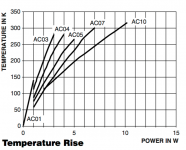
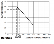
The power in a resistor is rated at an certain ambient temperature and in this case you have a derating curve up to 200 deg C. Notice that the temperature rise can be quite high for the bigger types, up to 300 degrees.
Vishay Draloric AC series
http://www.vishay.com/docs/28730/acseries.pdf
The power in a resistor is rated at an certain ambient temperature and in this case you have a derating curve up to 200 deg C. Notice that the temperature rise can be quite high for the bigger types, up to 300 degrees.
Attachments
Why no advantage? doesn't higher current makes\ the output impedance lower?
The resistor datasheet has graph that shows that the resistor shouldn't fail until 150 degree. But I am always worried when a resistor gets 90 degree, because it is nearly boiling temperature
I don't know if the Zout gets lower. Maybe it does; maybe not, but at any rate the difference would be minuscule. What is the total current draw?
And why would the boiling point of water be 'special' for a resistor??
Jan
Last edited:
From engineering point of view it seems not a good idea to burn energy in order to lower the output impedance a couple of micro ohms.
I have just simulated various current loads affecting the output impedance.
The improvement from output current of 10mA to 150mA is 13.38dB, or approximately 5 times. Or put it in another way, the output impedance when running on 150mA is only 21% of the output impedance when running on 10mA.
Is that worth of burning some heat?
The drawback may be the increase of temperature on the PCB from 30 degree to 50 degree may shorten the life of the small electrolytic capacitors on board.
Guys, have you read any datasheets?
Vishay Draloric AC series
http://www.vishay.com/docs/28730/acseries.pdf
The power in a resistor is rated at an certain ambient temperature and in this case you have a derating curve up to 200 deg C. Notice that the temperature rise can be quite high for the bigger types, up to 300 degrees.
In that datasheet, should TEMPERATURE IN K be TEMPERATURE IN Celsius?
My WW resistor is rated 5W so it is simular to that AC05, with 1.5W dissipation having the temperature close to 100 degree Celsius. If that is correct, then the resistor can stand much higher temperature before failing.
If a WW fails, will it fail short or open?
I have just simulated various current loads affecting the output impedance.
The improvement from output current of 10mA to 150mA is 13.38dB, or approximately 5 times. Or put it in another way, the output impedance when running on 150mA is only 21% of the output impedance when running on 10mA.
Is that worth of burning some heat?
The drawback may be the increase of temperature on the PCB from 30 degree to 50 degree may shorten the life of the small electrolytic capacitors on board.
Thtat's a big change indeed, hadn't expected that. Would be very interesting to know how it holds up in actual hardware.
What were the numbers you found?
Jan
About Kelvin vs. Celcius, I think you can figure out this. Ice is freezing at 273 K
That is to say that they have mistaken C to K in that data sheet.
Thtat's a big change indeed, hadn't expected that. Would be very interesting to know how it holds up in actual hardware.
What were the numbers you found?
Jan
I have not gone that far to measure the output impedance of a regulator. But with all voltage regulators I built they all have a lower output impedance when running on higher current.
Mr. Jung in one of his articles suggested running on at least 100mA for the Jung Super Reg.
AD825 Substitutions
I recently completed my project using the super regulator boards and it's sounding great. Aside from the AD817 and 797s, have people had success with other opamps. Has anyone found a sonic improvement over the AD825?
I have a number here including AD8610,49710,ADA4627. I haven't listened to any substitutions yet to see if there was a difference.
Please forgive me if this has been discussed. I couldn't find it in a search.
I recently completed my project using the super regulator boards and it's sounding great. Aside from the AD817 and 797s, have people had success with other opamps. Has anyone found a sonic improvement over the AD825?
LME49710 worked and sounds fine.
Thanks. I'll give it a try. I also have a bunch of LME49990s I might try. In fact, when I get a chance, I'll try what I have here and report back. I was hoping someone might have found one that they felt sounds significantly better.
Someone did say he didn't like the sound of the National Semi chips in this super reg, ie, 49990, 49710. But you might like them best, ie, equipment dependent, so please do post your findings 🙂
The AD797 appears to be the best performer on those graphs in Linear Audio but may require to be in a screened box. Seems they didn't test the 49990.
As a DAC output buffer, the TO99 was better sounding than the plastic chip version. But compared to the 49990 and 797 it had a overly soft and blurred sound with a lot more bass and too little treble. Tried it with a couple of difference DACs with same sonic result.
The AD797 appears to be the best performer on those graphs in Linear Audio but may require to be in a screened box. Seems they didn't test the 49990.
I have a few of these in the TO99 can. Maybe that screening would help with this Super Reg?LME49710 worked and sounds fine.
As a DAC output buffer, the TO99 was better sounding than the plastic chip version. But compared to the 49990 and 797 it had a overly soft and blurred sound with a lot more bass and too little treble. Tried it with a couple of difference DACs with same sonic result.
Last edited:
I have a few of these in the TO99 can. Maybe that screening would help with this Super Reg?
I don't think it will help...the Jung SR is lily not in need of that particular form of gilding. At the moment, all of my SR's use the AD825ar, two are on the original Old Colony boards and one is on Jan's newer board.
It could be my advancing years, but in listening the NE5534, to my ears, sounded a bit better than the venerated OPA637.
The AD797 appears to be the best performer on those graphs in Linear Audio but may require to be in a screened box. Seems they didn't test the 49990.
Indeed, it is a whizz-bang champ, but it can oscillate -- i think i posted a pic of it competing for bandwidth with WABC-AM at 770kHz quite a while back.
Last edited:
Do you have any pics of your project. Mine has been on hold for a few months now, still in the power supply snubber stage.
How do we think an op amp in the feedback circuit of a power supply affects sound quality other than its ability to deliver a low noise/ripple supply? Go for best PSRR (and perhaps low noise although it seems we're less sensitive to this) and be done, no?
Last edited:
How do we think an op amp in the feedback circuit of a power supply affects sound quality other than its ability to deliver a low noise/ripple supply? Go for best PSRR (and perhaps low noise although it seems we're less sensitive to this) and be done, no?
For his tests jackinnj on purpose used a line amp that is sensitive to supply ripple and noise (low PSRR).
Different regulators may have different output impedance characteristics and noise and ripple rejection, and using a sensitive line amp may lead to audible differences.
This differentiation is often not taken into consideration so you get in the situation that almost perfect supplies with very high PSRR line circuits still are thought to have audible differences. And the well-known psycho-acoustic phenomena and group think can do the rest.
So it is extremely difficult to decide which audible difference reports are realistic, and which not.
And don't forget that audible differences can only come from signal differences at the speaker posts which ultimately come from electrical signal differences elsewhere in the circuit and therefor are by definition measurable.
Jan
My question was more specific. For a given regulator circuit - in this case the Jung/Didden super-regulator - we expect audible differences between op amps (except insofar as they affect PSRR, noise and transient response)? Isn't the output impedance largely determined by the pass transistor and output capacitance?
My question was more specific. For a given regulator circuit - in this case the Jung/Didden super-regulator - we expect audible differences between op amps (except insofar as they affect PSRR, noise and transient response)? Isn't the output impedance largely determined by the pass transistor and output capacitance?
It's a feedback amplifier so most of the characteristics are defined by the feedback loop, it's gain and phase response. The output cap has almost no impact except for stability, the pass transistor is in the feedback loop so its properties are almost invisible.
Personally I would expect NO audible differences except with bad implementations/wiring, marginal stability and/or very low PSRR loads.
Jan
- Home
- The diyAudio Store
- Super Regulator