As I see it both polarity super regs are connected in reverse polarity. Your center tap/GND should go to the outside contacts of J1/J5 according to the silk screen picture in diyaudio store.
Regards,
Oleg
Regards,
Oleg
That's what I thought, too! Figure 1, in instructions is misleading.
This is the correct way to connect with a pre-regulator. The ground is on outside of J1 and J5. correct?

Now how to troubleshoot?
I am measuring
19.8v on positive reg.
-9.18v on negative reg
When turning on:
positive reg LED turns on shortly and goes off.
negative reg LED stays on.
Target output is +/-17v
This is the correct way to connect with a pre-regulator. The ground is on outside of J1 and J5. correct?
Now how to troubleshoot?
I am measuring
19.8v on positive reg.
-9.18v on negative reg
When turning on:
positive reg LED turns on shortly and goes off.
negative reg LED stays on.
Target output is +/-17v
That's what I thought, too! Figure 1, in instructions is misleading
Fig 1 is the circuit diagram, NOT a physical connection diagram!
Fig 2, the physical connection diagram, is correct as far as I can see.
Jan
No. D2 and D7 tests good. What part will likely fail if input polarity is reversed?
Last edited:
What supply voltages are the two super-regs expecting.Some smoke appeared so I assume -- problem! Anything wrong with this picture?
View attachment 602756..................
Splitting a +V, 0, -V dual polarity as you have shown, does not look right.
Expecting +/-21v, which is what I'm getting from the pre regulator. I have another pre regulator with separate output grounds. At this point just trying to figure out which parts are likely fried after connecting the Superreg backwards.
@Jan, not very natural to have the ground and Vin swapped. Why? It's very easy to make the mistake above.
@navigera, the opamp is most likely fried.
@navigera, the opamp is most likely fried.
Last edited:
PA,
It's been years since I layed-out that PCB and don't remember why it came out the way it did. For some reason the result was better or I wouldn't have done it.
But surely you wouldn't put parts on the board from their position on the schematic either?
Jan
It's been years since I layed-out that PCB and don't remember why it came out the way it did. For some reason the result was better or I wouldn't have done it.
But surely you wouldn't put parts on the board from their position on the schematic either?
Jan
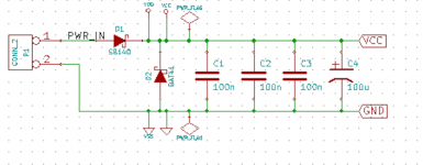
I've made the conscious decision to include protection against reverse polarity input, on all of the PCBs whose Gerber CAD files I give away here on diyAudio. I figure it's cheap insurance and the loss of headroom is tiny when you make D1 a Schottky type.
D2 might be gilding the lily a little. It's a 2nd safety net in case two bad things happen simultaneously: (a) the user connects the input voltage backwards; (b) D1's reverse leakage current is enormous. Then D2 clamps the negative voltage on |Vcc| to something less than a silicon diode drop.
D2 might be gilding the lily a little. It's a 2nd safety net in case two bad things happen simultaneously: (a) the user connects the input voltage backwards; (b) D1's reverse leakage current is enormous. Then D2 clamps the negative voltage on |Vcc| to something less than a silicon diode drop.
Attachments
@Jan, in case you need to do an upgrade of the pcb you could add "Vin", Gnd" etc. in the silkscreen and or on the solder side with copper text or text in the solder mask.
@Jan, in case you need to do an upgrade of the pcb you could add "Vin", Gnd" etc. in the silkscreen and or on the solder side with copper text or text in the solder mask.
Yes I will ask diyaudio when they are going to order new boards, I will provide an update.
Jan
A good point. But any advice for me so I can salvage the board? What parts should I replace?
My advice would be to strip the active devices, electrolytics and diodes and rebuild it. I'm sorry, but all these parts will be suspect even when on the face of it they seem to work. Stripping and rebuilding with new parts is by far the fastest and surest way. You may be able to re-use the opamps and the LM329's though, just try that after the rebuild.
Jan
Will do. Electrolytics look and measure good. Still replace them?
I would. They might have huge leakage after being reverse polarized and are not a big cost factor.
Will do. Definitely mark the future pcb. Or add a note in the assembly guide
Yes, it is very hard to make something fool-proof... 😉
Jan
Just when I was getting proud of myself 😉
It will make you stronger, grasshopper 😀
Jan
- Home
- The diyAudio Store
- Super Regulator