LEDs can be used as indicators that a current is flowing.
Red would be for an error situation and green for a good to go situation.
Leds can be used as a voltage reference. they are not particularly good at this because the voltage varies with temperature and with current. But if you regulate the current and manage to maintain a fairly constant Ta, then you can obtain a fairly low noise and stable voltage reference. Colour for these tends to be at the Long Wavelength end, i.e. IR, RED and orange.
Blue definitely NOT, white definitely NOT.
Yellow and green possibly OK, but worth experimenting to check for suitability.
Small adjustments to the reference voltage can be made by changing the current.
Big adjustments can be made by adding a signal diode (1n4148 or 914).
The LED's are for creating a voltage reference so the light is just a side effect. Blue, white and violett LED's will increase the minimum voltage drop of the regulator so if the input voltage is low then it's better to stick to red, yellow and green LED's.So, should I order 3mm green LEDs or will other colors work?
If you change to blue LED, then you'll have to adjust R1 and R8 to a higher value in order to keep the base current the same.
Blue and white leds are much noisier than red and green. ( around 10 times higher)
Red have the lowest noise with green having just a little higher voltage and noise according to Christer's testing a decade in DiyAudio ago. Noise varies with current as does the LEDS voltage drop. This varies by brand a little as well.
Best to use a constant source to supply them if you need a stable reference. Because the super regulator powers the reference from it's regulated output which reduces the need for a regulated current source to feed it.
Walt Jung in private correspondence with me indicated he had tried leds in the super regulator when I suggested trying them in the thread earlier.
" I have tried the multiple LED trick, and it does work, very well. Op amp noise will be the final limit however, as noted in the GLED431 blog cmnts. "
Last edited:
First post in thread needs links to be updated or delete the post and MOD a new opener to the thread.
 I think I've managed to get it back into currency 🙂
@ticknpop, we see from measurements made by jackinnj that the main contributor for the noise is the opamp only.
Thanks guys for all the info.
From what I gather from your replies, it sounds like a red LED is probably the best choice here.
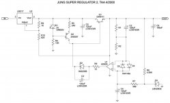
The schematic below shows a green LED with a 2V forward voltage.
Does the forward voltage have to be exactly 2V?
I see red LED's forward voltage can vary from 1.8-2.2V.
From what I gather from your replies, it sounds like a red LED is probably the best choice here.
The schematic below shows a green LED with a 2V forward voltage.
Does the forward voltage have to be exactly 2V?
I see red LED's forward voltage can vary from 1.8-2.2V.
Attachments
You will experience different max output current but I think it doesn't matter for you. By this you will also get different drop out voltage as I have mentioned earlier....
Does the forward voltage have to be exactly 2V?
I see red LED's forward voltage can vary from 1.8-2.2V.
Last edited:
red LEDs vary from ~1.6Vf to ~1.9VfThanks guys for all the info.
From what I gather from your replies, it sounds like a red LED is probably the best choice here.
The schematic below shows a green LED with a 2V forward voltage.
Does the forward voltage have to be exactly 2V?
I see red LED's forward voltage can vary from 1.8-2.2V.
IR are quite a bit lower.
All the other colours are higher.
Blue and white are very high Vf (=high watts = high brightness)
@kamis, you should have 5 volt or more difference between in and out and notice that this included the minimum voltage of the ripple. Can easily be determined by an oscilloscope.
@kamis, you should have 5 volt or more difference between in and out and notice that this included the minimum voltage of the ripple. Can easily be determined by an oscilloscope.
I remember that Walt Jung described 1995 version as a LDO regulator. Input on my 30V regulators is only 37V without mains voltage drop reserve.
Depends on your definition of LDO - things have changed the last 20 years.
The theoretical absolute minimum dropout of a superreg is of course the LED voltage + pass device Vbe. So about 2.5V absolute minimum, depending on the type of LED. The 5V recommendation is a good one.
Jan
The theoretical absolute minimum dropout of a superreg is of course the LED voltage + pass device Vbe. So about 2.5V absolute minimum, depending on the type of LED. The 5V recommendation is a good one.
Jan
Hasnt Linear Tech developed the "almost no dropout" regulator? They got on this "energy harvesting" kick...
Hasnt Linear Tech developed the "almost no dropout" regulator? They got on this "energy harvesting" kick...
Don't they use enhancement-mode MOSFETs as pass devices? That could lower the dropout into the mV range.
Jan
LTC3035 uses MOS source follower + charge pump voltage booster, to achieve 45mV dropout voltage at 300mA
LT3070 uses MOS common source amplifier (output from the drain), with no charge pump, to achieve 85mV dropout voltage at 5 amperes
LT3070 uses MOS common source amplifier (output from the drain), with no charge pump, to achieve 85mV dropout voltage at 5 amperes
Hello all,
I'm building a new control/preamp unit with a RIAA and a DAC onboard and needs no less than 7 single regulators and I really wanted to use the excellent Jung/Didden superreg.
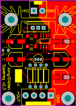
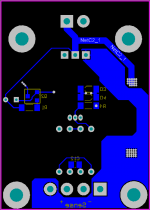
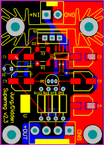
As the enclosure is given for the unit (read: small/medium size) 7 superegs in the original size wont fit. So I decided to make a SMD version.
The symmetrical placement of the components wasn't a goal of the design itself and just became natural during the layout process.
A few leaded resistors remains in the design to keep the noise as low as possible but I've properly screwed the performance with my PCB layout. 😀
Board size is: 35*49.3 mm
Now I need to do a sanity check of my layout and make the negative PCB version.
I'm building a new control/preamp unit with a RIAA and a DAC onboard and needs no less than 7 single regulators and I really wanted to use the excellent Jung/Didden superreg.
As the enclosure is given for the unit (read: small/medium size) 7 superegs in the original size wont fit. So I decided to make a SMD version.
The symmetrical placement of the components wasn't a goal of the design itself and just became natural during the layout process.
A few leaded resistors remains in the design to keep the noise as low as possible but I've properly screwed the performance with my PCB layout. 😀
Board size is: 35*49.3 mm
Now I need to do a sanity check of my layout and make the negative PCB version.
Attachments
Last edited:
Kim have you considered using a SilentSwitcher for compactness and totally mains free operation?
What voltages do you need?
Jan
What voltages do you need?
Jan
Kim have you considered using a SilentSwitcher for compactness and totally mains free operation?
What voltages do you need?
Jan
I indeed considered the SilentSwitcher. Nice toy! 😀
I need 5V, 9V, 12V and 15-18V.
On paper the supereg still looks as the reg with lowest noise and lowest impedance? The supereg also came out best of breed soundwise in linear audio... I'm in doubt about the SS.
I know it's all academic but my CDO(!) disorder always seems to get the last word in discussions with myself...
Can the SilentSwitcher compete soundwise with the supereg?
- Home
- The diyAudio Store
- Super Regulator