If they are not swollen they are probably OK. The opamp will with higher voltages experience instant destruction if you haven't limited the current.Will do. Electrolytics look and measure good. Still replace them?
Thanks. This gives me a good sequence of trial replacements
1. All diodes and small transistors
2. Opamps
3. Electrolytics
4. Big transistors
I'll report my finding after getting an order of new parts.
1. All diodes and small transistors
2. Opamps
3. Electrolytics
4. Big transistors
I'll report my finding after getting an order of new parts.
add a small power diode across the biggest electrolytic supply rail decoupling capacitor.
When you power on via a Mains Bulb Tester the diode should not pass and the bulb remains unlit.
When the supplies connected are incorrect, the diode passes and turns on the bulb. This lowers the secondary output voltage to a couple of Vac and saves everything.
When you power on via a Mains Bulb Tester the diode should not pass and the bulb remains unlit.
When the supplies connected are incorrect, the diode passes and turns on the bulb. This lowers the secondary output voltage to a couple of Vac and saves everything.
Almost there, almost...
>>Thanks. This gives me a good sequence of trial replacements
>>1. All diodes and small transistors
>>2. Opamps
>>3. Electrolytics
>>4. Big transistors
>>I'll report my finding after getting an order of new parts.
replaced:
1. All diodes and small transistors -- did not help
2. Opamps -- This worked!
I am almost there, just a bit off. All parts per BOM but I am getting +15.06/-14.8v @ THE LOAD (phono board)
Whats the best way to bring those values to a match?
Is it safe to assume the Electrolytics and Big transistors are ok?
THANKS for your help with this troubleshooting!
One side working, the other side: voltage too high
I'm having a problem with my super regulator.
I'm new to this, so not sure how to proceed.
Input DC is 31.4 V on both sides of the SR.
Output DC on the side that is working correctly is my expected 24.3 V and stable.
Output on the side not working correctly is 30.9 V and stable.
Symptoms:
LED on the side that is not working lights up, then flickers a few times as the capacitors charge when power is turned on (working side LED is steady throughout). After a few seconds the LED remains constantly lit.
When power is turned off the LED on the working side slowly fades. On the not working sided it goes off instantly (as if no capacitors are routing power to this LED).
Voltage across the 12 V zener diode is 12.4 V in the working side and 4.1 V on the not working side.
Any ideas what I should test or try to fix this?
Thanks
LT1028 instead of AD825
About using the LT1028 instead of AD825, back in post #103/104 Jan answered "Should be fine, probably as good as an '825". I'm building two, a +-10v and +12v. Just verifying will not loose anything by going with the LT1028 since Digikey has it in DIP8. Thanks.
About using the LT1028 instead of AD825, back in post #103/104 Jan answered "Should be fine, probably as good as an '825". I'm building two, a +-10v and +12v. Just verifying will not loose anything by going with the LT1028 since Digikey has it in DIP8. Thanks.
Noviygera- Assuming you used 1% resistors the regulators are likely working OK, the difference is likely the LM 329 tolerance. You can change the 329 to get the voltage you want, but don't damage the board
Noviygera- Assuming you used 1% resistors the regulators are likely working OK, the difference is likely the LM 329 tolerance. You can change the 329 to get the voltage you want, but don't damage the board
I agree. Another thing you can do if you want to tweak the voltage is to slightly tweak one of the feedback resistors with a // resistor. But I wouldn't take the trouble.
BTW Yet another way to get precision is to replace the LM329 with for instance an LM4040-5. These can be had with 0.5% accuracy. You need to adjust the feedback resistor ratio of course for the different reference voltage.
Maybe for V4 😉
Jan
I'm having a problem with my super regulator.
I'm new to this, so not sure how to proceed.
Input DC is 31.4 V on both sides of the SR.
Output DC on the side that is working correctly is my expected 24.3 V and stable.
Output on the side not working correctly is 30.9 V and stable.
Symptoms:
LED on the side that is not working lights up, then flickers a few times as the capacitors charge when power is turned on (working side LED is steady throughout). After a few seconds the LED remains constantly lit.
When power is turned off the LED on the working side slowly fades. On the not working sided it goes off instantly (as if no capacitors are routing power to this LED).
Voltage across the 12 V zener diode is 12.4 V in the working side and 4.1 V on the not working side.
Any ideas what I should test or try to fix this?
Thanks
What is the voltage at the opamp inputs and output?
What appears to happen is that the opamp draws down its output in an effort to lower the output voltage but not succeeding. So something is wrong around the current source feeding the base of the pass device, or the pass device itself. Check stuff around that area, compare with the good side.
Jan
Last edited:
Jan-
Op Amp voltages (bad side):
pin 2 =0.78 V
pin 3=0.93 V
pin 6 =24.1 V (on good side output is about 9.9 V, inputs about 0.78 V)
Zener Diode
bad side: 23.9 V and 29.5 V (about 6 V across)
good side: 9.8 V and 22.3 V (about 12 V across)
Pass Transistor:
bad side: center pin = 31.8; pin to V-out = 30.8 V; 3rd pin = 29.5 V
good side: center pin = 31.8 V; pin to V-out = 24.4 V; 3rd pin = 22.2 V
Something is off either with the op amp, or near the zener and pass transistor, but I don't know what??
Per-Anders - I should have mentioned that I do not have the SR outputs or sense connections hooked up to anything yet. So, just measuring from the output terminals.
I'll be tied up for a week or so, and get back to this later. Thanks for your help.
greg
Jan-
Op Amp voltages (bad side):
pin 2 =0.78 V
pin 3=0.93 V
pin 6 =24.1 V (on good side output is about 9.9 V, inputs about 0.78 V)
Zener Diode
bad side: 23.9 V and 29.5 V (about 6 V across)
good side: 9.8 V and 22.3 V (about 12 V across)
Pass Transistor:
bad side: center pin = 31.8; pin to V-out = 30.8 V; 3rd pin = 29.5 V
good side: center pin = 31.8 V; pin to V-out = 24.4 V; 3rd pin = 22.2 V
Something is off either with the op amp, or near the zener and pass transistor, but I don't know what??
Per-Anders - I should have mentioned that I do not have the SR outputs or sense connections hooked up to anything yet. So, just measuring from the output terminals.
I'll be tied up for a week or so, and get back to this later. Thanks for your help.
greg
I'm a bit busy right now, but if the opamp pin 3 is above pin 2 I expect the output to go high, which is what I see, so opamp seems OK.
So the opamp output goes high in an effort to open up the pass device more so that voltage at pin 2 also goes up to match the voltage at pin 3 but it is not happening. Again, it seems the CS feeding the base of the pass device is kaput or at least not supplying enough current.
You could try with the opamp removed and a bit of load, you should see almost the same output as the input voltage of the reg. If not, definitely the CS.
Or the pass device itself.
Jan
Edit: missed the point that the 6.9V reference of the LM329 to pin 3 is not there! Why not?? Is the LM329 in backwards?
Jan
Jan
First post in thread needs links to be updated or delete the post and MOD a new opener to the thread.
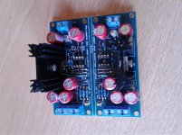
I purchased super regulators from DIY Audio Store and they seem to be fantastic! I can't wait to deploy them...soon. I think it is a relatively low cost solution with big results...from what I hold in my hands. My buddy at ADI sent me some free samples...that's always nice. These will do well in my B3A Pass preamp.
Double Cheers to Didden and Jung!!
Attachments
Should I bother using "audio grade" 120uf lytic capacitors or film bypass caps? Isn't it bad to have lytics for AC feedback at HF?
No.Should I bother using "audio grade" 120uf lytic capacitors or film bypass caps?
Not in this case as. It's all in the previous pages of this thread, spelled out exactly why 🙂Isn't it bad to have lytics for AC feedback at HF?
Ah good thanks 🙂
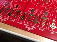
I'm building my own because I need higher voltages.
A couple at 50v and a couple at 200v.
First on my list is the 50v version.

Before I send it off to the fab do you see anything wrong with it?
I'm building my own because I need higher voltages.
A couple at 50v and a couple at 200v.
First on my list is the 50v version.
Before I send it off to the fab do you see anything wrong with it?
Last edited:
I'm trying to get a parts order together for this regulator.
On the BOM, for the LED it states "LED pitch 2.5mm".
In the photo of the DIY Store assembled board, I see green LEDs used.
So, should I order 3mm green LEDs or will other colors work?
Should the forward voltage be a certain value?
Are the LEDs just to verify voltage at the inputs or are they necessary for the circuit to work properly?
Thanks.
- Home
- The diyAudio Store
- Super Regulator