Nuryev, you may find assembly easier if you solder the low height components (axial resistors, diodes etc) before the tall components (electrolytic capacitors).
Regards,
Rick
Regards,
Rick
Thanks Rick. I found that out the hard way, but impatience got the better of me this time and I had to make a start, although some resistors hadn't arrived yet.
I purposely left the smd opamp for later as someone mentioned testing voltages before installing the opamp. It looks like that might have been a reference to socketed opamps.
I purposely left the smd opamp for later as someone mentioned testing voltages before installing the opamp. It looks like that might have been a reference to socketed opamps.
Yes, leave the opamp socket empty until some testing is completed successfully.Thanks Rick. I found that out the hard way, but impatience got the better of me this time and I had to make a start, although some resistors hadn't arrived yet.
I purposely left the smd opamp for later as someone mentioned testing voltages before installing the opamp. It looks like that might have been a reference to socketed opamps.
A soic leaves you no choice but to risk power on with the expensive opamp already in place.
You can use an 8 pin dip socket. Mount the soic opamp on an soic to 8 pin dip adaptar (Aries). Soldering the 8 pin soic to the pc board is better , but this will work OK.
Thanks Andrew.
I logged onto my computer for the regulator stuffing guide to confirm smd orientation, and found your message waiting for me! Your timing was great!
Are you able to point me in the right direction for testing?
I have a relatively good dvm, as well as oscilloscopes 20mhz and 50mhz.
I logged onto my computer for the regulator stuffing guide to confirm smd orientation, and found your message waiting for me! Your timing was great!
Are you able to point me in the right direction for testing?
I have a relatively good dvm, as well as oscilloscopes 20mhz and 50mhz.
opamp socket
Unfortunately, I was unable to get a suitable opamp for the socket option,so I had to go with the smd version.
You can use an 8 pin dip socket. Mount the soic opamp on an soic to 8 pin dip adaptar (Aries). Soldering the 8 pin soic to the pc board is better , but this will work OK.
Unfortunately, I was unable to get a suitable opamp for the socket option,so I had to go with the smd version.
Measure input voltages and measure the supply pin voltages on the soic.
Add a resistor to each supply lead and measure the current without the soic in place.
Leave the resistors in place for first power on with the soic soldered in.
Add a resistor to each supply lead and measure the current without the soic in place.
Leave the resistors in place for first power on with the soic soldered in.
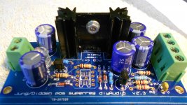
The pin next to the J1 text is the positive. As a double check it goes to the centre pin (collector) of Q1.
Regards,
Rick
Regards,
Rick
Without the opamp loaded, pin 3 of the opamp should measure about 6.9volts assuming:
- you have used the LM329 reference
- you have shorted the +ve output to the +ve sense input on J2
- the +ve return is shorted to the +ve return sense on J2
J2 has 4 connections, pin 1 at one end, pin 4 at the other. Short pins 1 and 2. Short pins 3 and 4. ie in this instance it does not matter which end you call pin 1
Also check the output voltage.
Because the opamp is not loaded the output is unregulated and will be higher than the regulated voltage.
Regards,
Rick
Unfortunately, I was unable to get a suitable opamp for the socket option,so I had to go with the smd version.
Just use any old cheap opamp for testing. If all is well you can always replace it with a boutique part 😉
Jan

Without the opamp loaded, pin 3 of the opamp should measure about 6.9volts assuming:
- you have used the LM329 reference
- you have shorted the +ve output to the +ve sense input on J2
- the +ve return is shorted to the +ve return sense on J2
J2 has 4 connections, pin 1 at one end, pin 4 at the other. Short pins 1 and 2. Short pins 3 and 4. ie in this instance it does not matter which end you call pin 1
Also check the output voltage.
Because the opamp is not loaded the output is unregulated and will be higher than the regulated voltage.
Regards,
Rick
Excuse the silly question.
Should I use a resistor to short J2 connections or will a wire jumper suffice?
Should I use a resistor to short J2 connections or will a wire jumper suffice?
I plan to instal the regs in a marantz cd63 or cd67.
Would an 18v 'wallwart' power supply be suitable option for testing?
I also have a 0.75va 2x15v encapsulated transformer that I could use to build a quick and simple power supply for this purpose.
Would an 18v 'wallwart' power supply be suitable option for testing?
I also have a 0.75va 2x15v encapsulated transformer that I could use to build a quick and simple power supply for this purpose.
0.75VA is tiny.
It will have a maximum continuous output of 0.75/(15+15) = 25mAac
That really is tiny.
If you rectify and smooth via a capacitor input filter, then your maximum continuous DC current is ~15mAdc. Drawing that will make it hot !
It will have a maximum continuous output of 0.75/(15+15) = 25mAac
That really is tiny.
If you rectify and smooth via a capacitor input filter, then your maximum continuous DC current is ~15mAdc. Drawing that will make it hot !
I plan to instal the regs in a marantz cd63 or cd67.
Would an 18v 'wallwart' power supply be suitable option for testing?
I also have a 0.75va 2x15v encapsulated transformer that I could use to build a quick and simple power supply for this purpose.
An 18V wallwart (assuming it is DC) is fine for testing. Since it is only one polarity (I guess) you need to test the pos and neg reg one at the time, but that's OK. This is like a go/no-go test.
For testing the neg reg, put the pos output of the wallwart to gnd, and the neg output of the wallwart to the neg reg input.
Jan
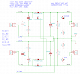
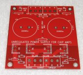
"a simple power supply for the super regs" sounds like you mean rectifiers, filter capacitors, and possibly other components, that produce filtered, but not regulated, "raw DC" as input to the super regulators.
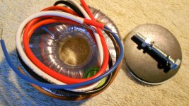
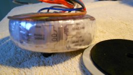
A fairly standard design, with typical components and typical circuit topology, is attached. "S1Dot" is the phase-dot end of secondary#1 , while "S1_ND" is the no-phase-dot end of secondary#1. Secondary#2 wires are named "S2Dot" and "S2_ND". "Shield" is the transformer's electrostatic shield (purple wire on an Antek AS toroid), if present. "To_Star" is the star ground. As shown, the supply produces +28V @ 4 amps and -28V @ 4 amps. With a 500mA Jung/Didden super reg, you would draw less than 4 amps, so maybe you might modify the circuit to use smaller capacitors and scrawnier diodes.
If you decide to keep the transformer snubbers (C1, C2, R2, etc) you will need to tune them for the particular transformer you are using. Search the forum for "snubber" and/or "Quasimodo" to learn more.
Attachments
Last edited:
- Home
- The diyAudio Store
- Super Regulator