Pass Q replaced. 10k soldered from raw DC to base pin. Raw DC is 15.25V. Base of Q1 is 13.06V
Output around 12.4V? And I guess the opamp is regulating now? Both inputs at around 6.9V?
Check that R7 is really 1k. Pin 2 should not be at 1.7V with or without the opamp present. If R7 is too low (say 100R) it will pull down the voltage at pin 2 and the diode between pins 2 and 3 will pull down the voltage on pin 3.
Pin 3 voltage should be about 6.9V providing the output voltage is above 8 volts. Pin 2 should equal pin 3 when the opamp achieves regulation.
If R7 is not the culprit there has to be something abnormal in the divider chain from Vout to pin 2 of the opamp.
Pin 3 voltage should be about 6.9V providing the output voltage is above 8 volts. Pin 2 should equal pin 3 when the opamp achieves regulation.
If R7 is not the culprit there has to be something abnormal in the divider chain from Vout to pin 2 of the opamp.

Purple is not a tolerance colour code.Here is pic. R7 has color code, brown, black, black, black, purple. That checks out to 1K by my calculations. I will pull at lunch and check out of the circuit.
The brown stripe must be the 1% tolerance code.
that makes your resistor striping to be: purple/violet, black, black, black, brown
for a 5 stripe you have 3 value codes, one multiplier code and one tolerance code. 710 * 1 @ 1% But that does not exist !
Violet would have to be followed by green for 75
That cannot be violet.
You need to measure that resistor. Maybe have to pull out one end to measure correctly.
I suspect that violet stripe is probably a discoloured brown stripe making a 100r resistor.
Last edited:
RGN is correct. IT appears to be 100ohms. 3rd stripe should be brown for a multiplier of 10. There is a .1% violet tolerance code. I will pull and confirm this evening. I still haev the 1K bag. I wonder if they were miss pulled. If so, I will put on my dunce hat and take a pic for all the trouble.
I take that back, violet, green and blue are valid tolerance codes.
I need to update my lack of knowledge bank.
I need to update my lack of knowledge bank.
I tihnk they were miss bagged. I populated the boards at two different times. I can see putting 100 omhs in the wrong place once, but not twice. I also have a 100ohm bag.
With a problem this intransigent, I would measure everything. Twice in my life I've seen mis-labeled resistors, it's a bugger to work out what's going on! The only solution is to measure everything.
Good advice. 100 ohms would indeed cause what we see, including the 3.something on the LM329.
But it does not explain an output with the B of the pass Q at zero, so that appears to be another issue, apparently solved with the removal of Q2.
I would say, fix the regulation first and then get back to the input circuit.
Note to builders: when building multiple units, finish one first before doing the others ;-)
Jan
All is well. I am sorry that such a bone headed mistake caused so much trouble. Also found 10R instead of 100r on r15/16. Other board has same exact mistakes. I have an empty bag of 1k resistors and a empty bag of 100r. Moved the 100r from r7/14 to r15/16. I still think they were miss bagged as I ordered exact number of resistors, but at this point I will tuck my tail and just be happy with the results🙂. Your welcome for the intellectual challenge of exploring the mind of a moron🙂
All is well. I am sorry that such a bone headed mistake caused so much trouble. Also found 10R instead of 100r on r15/16. Other board has same exact mistakes. I have an empty bag of 1k resistors and a empty bag of 100r. Moved the 100r from r7/14 to r15/16. I still think they were miss bagged as I ordered exact number of resistors, but at this point I will tuck my tail and just be happy with the results🙂. Your welcome for the intellectual challenge of exploring the mind of a moron🙂
Don't go so hard on yourself. Just learn the colour code better and observe what you're putting in.
Buzzforb, glad to hear tou got it going! I am planning on building a couple of super-regs. soon to power Richard Marsh's headphone amplifier.
I use to just look at the colour rings to check the resistor values when there were only 3 value bands and either a silver (10%) or gold (5%) tolerance band. But they now use up to 6, often narrow bands and it can be difficult to tell brown from red. Now I always measure before soldering to be sure.
Regards,
Rick
I appreciate the kind words, just feels like a stupid mistake. Been at this long enough that it shouldn't happen. Cheers to all for the help.
just feels like a stupid mistake
I have put a VOM test probe on the schematic at 2:00 a.m. and have been mucho irritated when I couldn't get a reading....duh
Although I don't put wrong value resistor in my circuits, when I do make a mistake it is much more serious and costly to resolve.
A famous quote, "A man has got to know his limitations".
Doing electronics without sufficient sleep is one of them.
A famous quote, "A man has got to know his limitations".
Doing electronics without sufficient sleep is one of them.
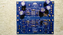
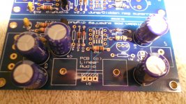
Hi all, I have started on my super regulator build.
Thanks Jan for assistance.
Progress is slow as I have to wait for parts that are not available.
I have taken some good advice and started measuring and checking components before soldering.
Pics are included.
Any comments or advice will be appreciated.
Thanks Jan for assistance.
Progress is slow as I have to wait for parts that are not available.
I have taken some good advice and started measuring and checking components before soldering.
Pics are included.
Any comments or advice will be appreciated.
Attachments

- Home
- The diyAudio Store
- Super Regulator