oh thanks lhquam!
you mean I can do this in Spice….. ?
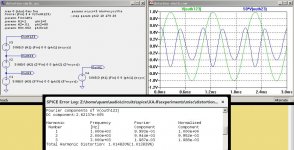
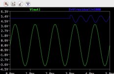
If you examine the residual waveform V(out)-K*V(In) (unfortunately not corrected for the minor phase shift of the output), you will see negative H2 phase
you mean I can do this in Spice….. ?
If you examine the residual waveform V(out)-K*V(In) (unfortunately not corrected for the minor phase shift of the output), you will see negative H2 phase
oh thanks lhquam!
you mean I can do this in Spice….. ?
If you examine the residual waveform V(out)-K*V(In) (unfortunately not corrected for the minor phase shift of the output), you will see negative H2 phase
Sounds like K is about V(out)/V(in). To see the residual waveform, run your simulation and then right-click (if using Windows) on the graph title. You can then type the formula with your value of K in the window that opens, yes?
Last edited:
Since I had one of these a few feet away, I pulled up a quick measurement -
the sim thd number is low by a factor of about 3, but the relative ratio
of H2 to H3 is about 26 dB in mine, not 20.
😎
the sim thd number is low by a factor of about 3, but the relative ratio
of H2 to H3 is about 26 dB in mine, not 20.
😎
Last edited:
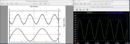
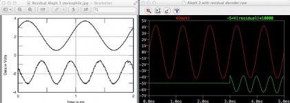
Here is a simple way to visualize the relationships between the distortion residual waveform and the LTSpice Fourier log file information. In the LTSpice example below, the Fourier magnitude and phase information is used the synthesize the waveform from the sums of H1 (the fundamental), H2 and H3. The waveforms are of the total sum and the residual magnified by a factor of 50. I also include the .asc file for you to play with.
Attachments
Spice residuals
O.k. guys I tried all three ways …..
lhquam first proposal the hard way….. 🙂)
lhquam second proposal the soft way 🙂)
and this luxury version from jcx
http://www.diyaudio.com/forums/software-tools/101810-spice-simulation-37.html#post1333137
doing all for you when you copy the machine at the output, take his Spice directives and his way of signal source description.
so my hope to find out that the real secret of the Aleph3 was the early use of negative phase k2 by Nelson
was futile…..🙂)
Both Amps Aleph3 and Aleph30 seem to work with pos phase k2.
I could change the Aleph 3 to neg. phase k2 by enlarging the Aleph feedback resistor from 750R to a much higher value or you omit two of 0R47 sense resistors.
was futile…..🙂)
Both Amps Aleph3 and Aleph30 seem to work with pos phase k2.
I could change the Aleph 3 to neg. phase k2 by enlarging the Aleph feedback resistor from 750R to a much higher value or you omit two of 0R47 sense resistors.
Sounds like K is about V(out)/V(in). To see the residual waveform, run your simulation and then right-click (if using Windows) on the graph title. You can then type the formula with your value of K in the window that opens, yes?
Thanks needtubes for breaking it down for my understanding!
🙂🙂
Both Amps Aleph3 and Aleph30 seem to work with pos phase k2.
Are you deciding this by looking at the upside down graphic?
😎
yes, not correct….?
I would never use this Spice sh**, if I had a device that shows the real residual….
so much traps…...
I would never use this Spice sh**, if I had a device that shows the real residual….
so much traps…...
Last edited:
HUHUH…..
I thought it could be negative phase because of the sound descriptions…. in the reviews.
THX!
I thought it could be negative phase because of the sound descriptions…. in the reviews.
THX!
- Home
- Amplifiers
- Pass Labs
- The Aleph Design Reloaded