Hu, hu the master is laughing…..
seems our answers have the character of "random parts" and no connection to the real sense of the parts on the table……
hu, hu!
Laser Cat game…. seems he has too much free time….. 🙂)))
seems our answers have the character of "random parts" and no connection to the real sense of the parts on the table……
hu, hu!
Laser Cat game…. seems he has too much free time….. 🙂)))
been there , slipped so many times .... so , no more Photoshop augmenting of Papa's random pictures
all I got every time is headache,while Pa only can get better abdominal musculature

all I got every time is headache,while Pa only can get better abdominal musculature
One man's trash can become another man's treasure! 🙂You guys are sooo entertaining. I think I'll regularly post a picture of parts
randomly attached on my bench and let you go at it.
...
😎
…...if any one wants to adjust or check the 50% Aleph CCS contribution in his Aleph30 or any other Aleph build
I found this from Nelson some in an old Aleph30 thread, very helpful:
"When you parallel devices in an Aleph but want to
vary the bias per device, you look to the value
of the Source resistances on the current source
(the bank on the positive half), and also (referring
to the Aleph 60 schematic) resistor R19. After you get the DC figure you are looking for, you
want to adjust the AC gain of the current source so
that the current source provides about 50% of the
output AC current. The easiest way to do this is to build the circuit
without R21 and operate it at 10 watts or so into a
load while measuring the AC voltage across R46-51
which are the Source resistors on the negative half
of the amp. Put in a value for R21 which halves
the AC voltage across R46-51, and you'll know that the current source is doing half the work." Hope this helps!
Yeah it did Master, really easy peasy! 😀😀😀
I adjusted the bias of my Aleph 30 to 1.8A for one channel. There for I had to change the 47k R19 to 33k and for the 50% contribution I had to go for 970R instead of the 850R for R21 in the Service manual of Aleph30.
Last edited:
been there , slipped so many times .... so , no more Photoshop augmenting of Papa's random pictures
all I got every time is headache,while Pa only can get better abdominal musculature
When I send him pictures of my builds his abdominal musculature still gets more strong…..🙂
…...if any one wants to adjust or check the 50% Aleph CCS contribution in his Aleph30 or any other Aleph build
I found this from Nelson some in an old Aleph30 thread, very helpful:
...
I was under the impression from another post I saw on the forums that one sets the AC current gain by varying the value of R21 until the AC voltage across one of the source resistors of the top FETs was half that of AC voltage across the current sense resistor in series with the output (this assuming the current sense resistor is a parallel bank of resistors - one for each output device - all of the same value of the source resistors). These two procedures seem give similar values of R21 (within 100-ohm in my SPICE simulation), but I suspect the one you mention gives the more appropriate setting, yes?
call me naive , for me (understanding of nomenclature - 50%) is that two halves are having equal contribution
so - same/equal AC reading across lower and upper source resistors
so - same/equal AC reading across lower and upper source resistors
And he has fine taste in wine, as seen here on my bench.
😎
Nelson: I notice you are using a Tek TDS2014C oscilloscope. I have a fully functional Tektronix 465B, but have considered using a digital scope. Can you impart your experience and opinion about digital vs. analog scopes?
It would also be nice to understand your technical approach to circuit breadboarding. 😀
I have a fully functional Tektronix 465B, but have considered using a digital scope. Can you impart your experience and opinion about digital vs. analog scopes?
I'm not Nelson (obviously... 😀 ) but I can answer that easily - digital scopes are awesome! If for no other reason than digital scopes have all the counters 'built in.' See some HF hash on the output? the digital scope will simply display that it's at 2.456mHz, (or whatever) and you don't need to dig in and figure it out and hope your resolution is good enough and the oscillation consistent enough to determine by squinting at the graticule.
Also can do nifty thing like display your V Pk-Pk in V RMS, or whatever else you choose. FFT, gates, screenshots, data logging, lots and lots of useful functions. And all I've got is a cheap Rigol.
I have a nice analog Toshiba that's still great for lots of uses - I don't plan on getting rid of it any time soon. But honestly, I grab for the digital scope first, as it displays a great many things in addition to the waveform.
Last edited:
since Papa seems to frequent this thread I will just drop a reference to my question in BA-3b thread:
http://www.diyaudio.com/forums/pass-labs/201281-burning-amp-ba-3b-balanced-56.html#post4790663
sorry for the distraction. now back to Aleph discussion 😉.
http://www.diyaudio.com/forums/pass-labs/201281-burning-amp-ba-3b-balanced-56.html#post4790663
sorry for the distraction. now back to Aleph discussion 😉.
Nelson: I notice you are using a Tek TDS2014C oscilloscope. I have a fully functional Tektronix 465B, but have considered using a digital scope. Can you impart your experience and opinion about digital vs. analog scopes?
It would also be nice to understand your technical approach to circuit breadboarding. 😀
I have historically had a few Tek analog scopes, starting with a 465 and then
a 475 and currently a 2215. I use them to see stuff that the digital scopes
might not catch at high frequencies.
The digital scopes have lots of conveniences including averaging, FFT and
image capture that make life easier. I have four of those.
My breadboarding approach reflects the most recent advances in Chaotic String Theory...
😎
To probably most of us your breadboarding reflects M-theory where M means Mystery.I have historically had a few Tek analog scopes, starting with a 465 and then
a 475 and currently a 2215. I use them to see stuff that the digital scopes
might not catch at high frequencies.
The digital scopes have lots of conveniences including averaging, FFT and
image capture that make life easier. I have four of those.
My breadboarding approach reflects the most recent advances in Chaotic String Theory...
😎
I recently got myself a Siglent SDS1102x, 8 inch color screen, 100MHz, 14Mpts memory, down to 500uV/div sensitivity and a small footprint. There are a few Chinese scopes on the market that are quite interesting, namely by Owon, Rigol or Siglent. Check YouTube for numerous reviews. I'm really happy with mine.
Attached you'll find a pic of the scope showing the input signal to my Aleph headphone amp in yellow and the residual distortion signal (2nd harmonic in character) in violet, taken from a test load at the amp's output. The residual distortion signal was generated by the bulky Boonton underneath the scope.
Attached you'll find a pic of the scope showing the input signal to my Aleph headphone amp in yellow and the residual distortion signal (2nd harmonic in character) in violet, taken from a test load at the amp's output. The residual distortion signal was generated by the bulky Boonton underneath the scope.
Attachments

A small confusion from an amatuer:
The thread starts out with NP talking about aleph 30s. Most of the discussion is around aleph 3. I know they are strongly related, but can i apply the advice re aleph 3 to an aleph 30?
The thread starts out with NP talking about aleph 30s. Most of the discussion is around aleph 3. I know they are strongly related, but can i apply the advice re aleph 3 to an aleph 30?
some news and irritation on my Aleph trip
I occupied more with Aleph 30 and Aleph 3…...🙂
Aleph 30 is running and sounds fine as you know.
Of course I wanted to build now not only the small case Aleph 30 with 40W at 4 Ohm but also the "real" thing, the Aleph 3 with 60W at 4 Ohm and the bigger PSU.
Parts are ordered…. meanwhile I spiced a bit….. 🙂
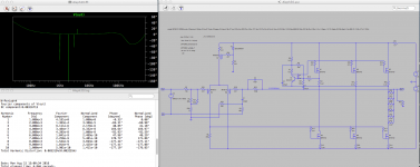
The first pictures shows the Aleph 3 data, the phase diagram from the THD and the Spice error log showing the distortion and the phase degrees.
The phase diagram shows what I thought would be negative k2 phase because the peaks goes in the inverse direction of the 1kHz peak.
But I also learned that the numbers shown in the Spice error log correlate with the picture in a way I seem not to understand fully.
The degree value shown in the picture where the 1kHz peak ends, seems to be the "zero" point for the degree numbers of the higher distortion peaks k2 and k3 in the column presentation.
So the column seems to say that the k3 peak ends in a value 21° more positive than the k1 value.
But the k2 peaks goes to nearly +180° and the difference to the k1 peak is more than the -81° mentioned in the column. Neither value nor numbers seem to fit
😕😕😕
May be someone can help me or is the culprit Spice?
Let us go to the Aleph 30 picture and data.
Here things between column and picture are more consistent.
K2 and k3 points at the end of the peaks correlate with their values well with the k1 zero point.
But here the k2 peak is only more negative than the k1 peak or longer downwards.
Now the final question…. 🙂)
Is this behavior of the Aleph 30 showing "negative phase" in the sense Nelson was using when he explained the F6 distortion tango? Because the k2 peak value is more negative than the k1 value?
Or it is a must that the peak of k1 and k2 must be going in inverse direction to have "negative phase".
Any comments welcome!
I occupied more with Aleph 30 and Aleph 3…...🙂
Aleph 30 is running and sounds fine as you know.
Of course I wanted to build now not only the small case Aleph 30 with 40W at 4 Ohm but also the "real" thing, the Aleph 3 with 60W at 4 Ohm and the bigger PSU.
Parts are ordered…. meanwhile I spiced a bit….. 🙂
The first pictures shows the Aleph 3 data, the phase diagram from the THD and the Spice error log showing the distortion and the phase degrees.
The phase diagram shows what I thought would be negative k2 phase because the peaks goes in the inverse direction of the 1kHz peak.
But I also learned that the numbers shown in the Spice error log correlate with the picture in a way I seem not to understand fully.
The degree value shown in the picture where the 1kHz peak ends, seems to be the "zero" point for the degree numbers of the higher distortion peaks k2 and k3 in the column presentation.
So the column seems to say that the k3 peak ends in a value 21° more positive than the k1 value.
But the k2 peaks goes to nearly +180° and the difference to the k1 peak is more than the -81° mentioned in the column. Neither value nor numbers seem to fit
😕😕😕
May be someone can help me or is the culprit Spice?
Let us go to the Aleph 30 picture and data.
Here things between column and picture are more consistent.
K2 and k3 points at the end of the peaks correlate with their values well with the k1 zero point.
But here the k2 peak is only more negative than the k1 peak or longer downwards.
Now the final question…. 🙂)
Is this behavior of the Aleph 30 showing "negative phase" in the sense Nelson was using when he explained the F6 distortion tango? Because the k2 peak value is more negative than the k1 value?
Or it is a must that the peak of k1 and k2 must be going in inverse direction to have "negative phase".
Any comments welcome!
Attachments

I occupied more with Aleph 30 and Aleph 3…...🙂
Aleph 30 is running and sounds fine as you know.
... Is this behavior of the Aleph 30 showing "negative phase" in the sense Nelson was using when he explained the F6 distortion tango? Because the k2 peak value is more negative than the k1 value?
Or it is a must that the peak of k1 and k2 must be going in inverse direction to have "negative phase".
Any comments welcome!
My understanding is the later: when the fundamental has a positive peak, H2 should be near a negative peak. It you examine the residual waveform V(out)-K*V(In) (unfortunately not corrected for the minor phase shift of the output), you will see negative H2 phase when the LTSpice log file shows H2 Fourier normalized phase or near -90 degrees. The value of K is very near CLG, but must be carefully tweaked to about 5 or 6 decimal places to properly null the fundamental. Try it.
- Home
- Amplifiers
- Pass Labs
- The Aleph Design Reloaded