Look here....
http://www.diyaudio.com/forums/pass-labs/267857-aleph-design-reloaded-28.html#post4808222
The 1022 FIR filter for the range 1500.-3500 seems change time alignment.
David advices to extract only from point 512 - end of file.
This seemS to make the correct time alignment with the fundamental wave.
I would never have found this.
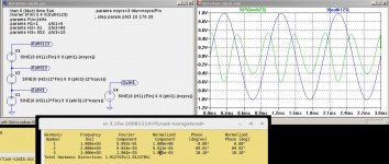
I plan to show the different results you get with Spice and the Aleph 3 circuit as well ....hope you have an eye on it and I am sure you can help to find the reasons why Spice used by an unexperienced user delivers contradictory results concerning the k 2 phase.
http://www.diyaudio.com/forums/pass-labs/267857-aleph-design-reloaded-28.html#post4808222
The 1022 FIR filter for the range 1500.-3500 seems change time alignment.
David advices to extract only from point 512 - end of file.
This seemS to make the correct time alignment with the fundamental wave.
I would never have found this.
I plan to show the different results you get with Spice and the Aleph 3 circuit as well ....hope you have an eye on it and I am sure you can help to find the reasons why Spice used by an unexperienced user delivers contradictory results concerning the k 2 phase.
Last edited:
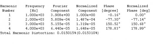
I just realized that my post in #245 http://www.diyaudio.com/forums/pass-labs/267857-aleph-design-reloaded-25.html#post4802935 did not show the harmonic phases. Note the plots show negative K2 phase whereas the numerical value of K2 phase in the log file is near +90 degrees. My comment in post #240 about the numerical value being near -90 degrees WAS INCORRECT. Here is what I intended to show:
Attachments
yes I know, let us discuss….
🙂
are these data in the error log made without any window?
no "Blackman" or something like this?
and are these numerical data the same data I see in the graphical FFT picture when I choose no window function?
🙂
are these data in the error log made without any window?
no "Blackman" or something like this?
and are these numerical data the same data I see in the graphical FFT picture when I choose no window function?
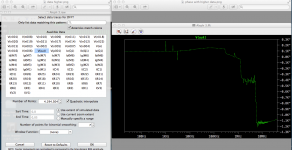
same routine I'm always using
run , after that right click on graph , see error log
prior to anything - disabled all compressions in control panel
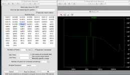
regarding FFT - 4M data point samples , number of points 7 , Hamming windowing function
run , after that right click on graph , see error log
prior to anything - disabled all compressions in control panel
regarding FFT - 4M data point samples , number of points 7 , Hamming windowing function
The Fourier data in the log file is not identical to the FFT plots, but there are quite similar and do not suffer from phase shifts due to the windowing functions. The windowing functions are totally symmetric and thus do not phase shift. In the plots of post #283, theta= 360*time/1ms K1(theta) = H1*sin(theta) relative phase of K1 to itself is zero K2(theta) = H2*sin(2*theta+90) relative phase of K2 to K1 is +90 degrees
I just realized that my post in #245 http://www.diyaudio.com/forums/pass-labs/267857-aleph-design-reloaded-25.html#post4802935 did not show the harmonic phases. Note the plots show negative K2 phase whereas the numerical value of K2 phase in the log file is near +90 degrees. My comment in post #240 about the numerical value being near -90 degrees WAS INCORRECT. Here is what I intended to show:
Does this mean that you can have neg phase k2 but degree value in the log is positive as shown in our last picture.....?
Does this mean that you can have neg phase k2 but degree value in the log is positive as shown in our last picture.....?
Yes.
In the plots of post #283,
- theta= 360*time/1ms
- K1(theta) = H1*sin(theta)
- relative phase of K1 to itself is zero
- K2(theta) = H2*sin(2*theta+90)
- relative phase of K2 to K1 is +90 degrees
for (audio)phool like Mighty Moi , there is greater possibility to buy AP One** (or something ) , than grasp my already short-circuited head around all math models and routines
**and maybe someday learn how to use most basic function of it ;however , not likely .....considering greenies involved

**and maybe someday learn how to use most basic function of it ;however , not likely .....considering greenies involved
Indeed that would be fine......AP one, dreaming.?....😛😛
So Spice remains the poor Germans the food giving mostly nice informations.......
🙂
So Spice remains the poor Germans the food giving mostly nice informations.......
🙂
I just realized that my post in #245 http://www.diyaudio.com/forums/pass-labs/267857-aleph-design-reloaded-25.html#post4802935 did not show the harmonic phases. Note the plots show negative K2 phase whereas the numerical value of K2 phase in the log file is near +90 degrees. My comment in post #240 about the numerical value being near -90 degrees WAS INCORRECT. Here is what I intended to show:
@lhquam
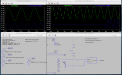
Do you know why the two residual programs distortion sim and the distortion decoder deliver the wrong phase residual for Aleph3 in Spice simulation,
or do I make a fault?
I used the circuit with the small correction of Nelson here
http://www.diyaudio.com/forums/pass-labs/267857-aleph-design-reloaded.html#post4184920
THX
left distortion SIM and right the residual decoder results
Attachments
The plot on the right showing positive K2 phase doesn't make sense since it also shows negative K3 phase, which seems unlikely. Was the right plot with higher output Wattage?
no only with a higher number of points chosen….same circuit same in and output.
I wanted to show that simply changing the number of points gives another information.
I wanted to show that simply changing the number of points gives another information.
So there seems to be be no explanation why the Aleph 3 spice simulation tools, that show the residual, are wrong showing pos phase k2. In real, the Aleph 3 shows neg phase k2.
Nelson told that the use of the Toshibas is a significant improvement in this circuit.
Some weeks ago I tried them instead of my Vishay 9610, but I still prefered the latter.
A more close look on his actual circuit showed that he seems to augment the output bias resistor from 47k to 56k and he lowered the 750R for the Aleph current source contribution
to 680R.
In my experience lowering this value gives a sound with more body. I did not like so much the Toshibas because they sound more bright or HiFi like at a quick look.
With the lower 680R I supposed they would sound more embodied.
So I tried yesterday one channel with the Toshiba and the new values and one with the Vishay 9610 and the old values 47k/750R.
Now the race was more close....
With Vishays I see still more body, a bit more distant, voices still heavenly, but a bit more veiled, and some percussion elements overly present
The Toshibas give more clarity and crispness, detail and more punchy bass.
O.K. Mr. Pass, I gave them a chance and put them in the second channel too.....
😀😀😀
Last edited:
possible, I did not try this…. 🙂), why do you want to do this?
my Speakers are 96dB/1W.
I find it a very attractive solution up to 30W at 8 Ohm speakers, easy to build, very good sounding in its specs.
And we have the Aleph0 and 1 and so on with so much Watts…..so I see no reason to go over the class A limit.
But maybe you want to say something I do not yet understand…. 🙂)
best regards to Vietnam
generg
Last edited:
- Home
- Amplifiers
- Pass Labs
- The Aleph Design Reloaded