From what I've read there are not all that many opamps that are stable in this circuit. I haven't simulated it though.
Hi,
After some tests on a breadboard (only the diamond buffer without opamp.), I am currently working on a layout.
I had some difficulties to get the circuit stable. Well, a breadboard is not the optimum for such circuits, a lot of stray capacitance, to long connectors....etc. But in the end I managed it to work stable.
It seems to me that the buffer itself tends to instability and I´m not sure if it´s a matter of opamps.
So, do you remember where you have read about the stability issues?
thanks in advance
I just solder the 6800uF Mundorf Mlytic caps and then I would like use a pair of AD744.

Muses01 is an interesting option based on Jfet too but is expensive. 😱😱
That opamp is jfet based with an adjustable CCS per channel.
Muses01 is an interesting option based on Jfet too but is expensive. 😱😱
Hi,
After some tests on a breadboard (only the diamond buffer without opamp.), I am currently working on a layout.
I had some difficulties to get the circuit stable. Well, a breadboard is not the optimum for such circuits, a lot of stray capacitance, to long connectors....etc. But in the end I managed it to work stable.
It seems to me that the buffer itself tends to instability and I´m not sure if it´s a matter of opamps.
So, do you remember where you have read about the stability issues?
thanks in advance
I think it was in a thread I started when my old BCL clone started misbehaving. Writing from my phone, so a short answer for now.
Hi
Thanks for the hint 🙂, I think I´ve found it: http://www.diyaudio.com/forums/headphone-systems/278128-fault-finding-bcl-clone-help-needed.html
Thanks for the hint 🙂, I think I´ve found it: http://www.diyaudio.com/forums/headphone-systems/278128-fault-finding-bcl-clone-help-needed.html
Hi
Thanks for the hint 🙂, I think I´ve found it: http://www.diyaudio.com/forums/headphone-systems/278128-fault-finding-bcl-clone-help-needed.html
That's the one 🙂
With the jfet discrete opamp, I got the DC offset trimmed very close to zero on that BCL clone.
Mlytic on the PSU is a big upgrade. Clear and dynamic sound. 😱
With the "Gold Tune" is more "hot"; heavy bass and treble are duller.
Now, I´m listening a dual mono pcb with a pair of AD744. 🙄
With the "Gold Tune" is more "hot"; heavy bass and treble are duller.
Now, I´m listening a dual mono pcb with a pair of AD744. 🙄
Mlytic on the PSU is a big upgrade. Clear and dynamic sound.
Nice to hear that, I still have a pair of 6800µF/63V left, so I decided right now to use them in my project.

I may or may not upgrade to 10000uF/50V panasonic ha lytics. For now I've done some mods to the existing setup by paralleling 3.3uf, 0.22uF and 0.1uF under each of the two 6800uF PS caps.
I also put an OPA1652 in there as per the advice from Clavefremen(I hope I got your name right) in another thread.
I also put an OPA1652 in there as per the advice from Clavefremen(I hope I got your name right) in another thread.
Last edited:
OK, i have a lot of Questions! Sorry!
hey, i made some progress and i have questions , to every question i will add pictures for convenient, thnx.
1. i got most of the parts, i started popualte. i know resistors dont have polarity but i have found few spots that i am not certain about them, they are all marked in the picture
so just tell me if they have some polarity.
wima FKP 1000P 63v
the two yellow fuses
the Amtrans AMCH 100P Caps
pic:
http://oi64.tinypic.com/2cyo4zo.jpg
2.another question in the amtrans area there is 4 holes that left do i need to solder something to there?
pic:
http://oi64.tinypic.com/5l0ys2.jpg
3. the 4 Wima MKP10 0.1uf 400v that i bought from here
http://www.mouser.com/ProductDetail...=sGAEpiMZZMv1cc3ydrPrF6kAfBcSzk7ffsOERk1ggDk=
is too big and not fit toghter what is the proper size that i need?
pics:
cap size-
http://oi68.tinypic.com/2rqdsef.jpg
board area
http://oi67.tinypic.com/sm6np5.jpg
4. the pcb terminal sit on the 3 pcb holes but there is 6. is this right to put them like this?
pic:
http://oi63.tinypic.com/3589vrq.jpg
5. there are 3 spots that i dont sure if i bought the right pieces. 680ohms,47ohms, 4.7ohms.
. i bought resitors from the Bom that cleve gave me but i am not excatly sure if they will fit because one of them is 681ohms not 680ohms and the other is is 4.75ohms not 4.7.
now there are 3 areas in the board that i will put 1W resistors. 2 X47r and one area of 10r. there are another 47 small area and by the bom this part is also 1w is it correct., shouldnt it be 1/8?
pic:
http://oi63.tinypic.com/kq8us.jpg
6. i bought a ceramic fuse for the IEC is it ok? its not the transarnt blow glass fuse. will it fit? the size is proper.
7. there some area that i bought stryoflex caps but they are huge and wont fit, i want some recomenation on the right caps, i prefer Wima or better, just mention Values (VDC,pf,uf) and size.
pic:
http://oi65.tinypic.com/f3yfq8.jpg
8. the sapcers that i will use to mount the board to the chassis is made of aluminium i want to ask if its ok to mount it like that or do i need some plastic washer isolation to prevent some
sort of damage to the amp or static electricity?
pic:
http://oi64.tinypic.com/i1gnco.jpg
thnx for the helpers!
Last edited:
1. No polariry
2. Other cap type
3. Antivirus
4. It´s OK 6 hole is for spares
5. Antivirus
6. Antivirus
7. Antivirus
8. Antivirus...
PLease if is possible, insert the imágenes right.
Mayday, Why they use those values?
2. Other cap type
3. Antivirus
4. It´s OK 6 hole is for spares
5. Antivirus
6. Antivirus
7. Antivirus
8. Antivirus...
PLease if is possible, insert the imágenes right.
Mayday, Why they use those values?
I feel more comfortable using a few different value caps as opposed to the "norm", not sure why.
Something I started doing long ago, don't even remember why.
Something I started doing long ago, don't even remember why.
1. i got most of the parts, i started popualte. i know resistors dont have polarity but i have found few spots that i am not certain about them, they are all marked in the picture
so just tell me if they have some polarity.
They have no polarity, they will work either way.
There's always a better sounding direction but unless you're willing to test each part using sockets... don't bother about it.
2.another question in the amtrans area there is 4 holes that left do i need to solder something to there?
The two on the center. Don't bother about the other two, they're there for a different type of cap.
3. the 4 Wima MKP10 0.1uf 400v that i bought from here
(...)
is too big and not fit toghter what is the proper size that i need?
All the parts that I've indicated in my BOM are a perfect fit.
Just paste in Mouser the part indicated in BOM so you can see what is the correct lead spacing for the part you want to use.
Or even simpler... just buy the part I've indicated... 😉
4. the pcb terminal sit on the 3 pcb holes but there is 6. is this right to put them like this?
Those positions are for faston tabs, you can use this Mouser code: 534-1287
5. there are 3 spots that i dont sure if i bought the right pieces. 680ohms,47ohms, 4.7ohms.
. i bought resitors from the Bom that cleve gave me but i am not excatly sure if they will fit because one of them is 681ohms not 680ohms and the other is is 4.75ohms not 4.7.
They will work, the difference is too small to be a problem.
Usually metal film resistors have 1% tolerance so, for instance, acceptable values for the 680 Ohm are between 673.2 and 686,8.
now there are 3 areas in the board that i will put 1W resistors. 2 X47r and one area of 10r. there are another 47 small area and by the bom this part is also 1w is it correct., shouldnt it be 1/8?
No, Lehmann used 1W ones for a reason... those resistors dissipate a significant amount of power...
There are 8 of them.
Pay attention though that 2 47R resistors, the one you marked with a question mark are 0207 format so 1/8W or 1/4W.
If you bought PTF56 the best sounding direction is reversed (markings reads on opposite direction Vs signal flow)
6. i bought a ceramic fuse for the IEC is it ok? its not the transarnt blow glass fuse. will it fit? the size is proper.
Nice choice, ceramic fuses usually sound better than glass ones.
7. there some area that i bought stryoflex caps but they are huge and wont fit, i want some recomenation on the right caps, i prefer Wima or better, just mention Values (VDC,pf,uf) and size.
Use the Wima FKP2 I've indicated in BOM, they're excellent sounding caps.
8. the sapcers that i will use to mount the board to the chassis is made of aluminium i want to ask if its ok to mount it like that or do i need some plastic washer isolation to prevent some
sort of damage to the amp or static electricity?
Don't worry, all mounting holes are insulated, except the one with a resistor and cap in the surrounding, that one connects the board to the case ground.
The case should be connected to protective earth.
Last edited:
I feel more comfortable using a few different value caps as opposed to the "norm", not sure why.
Something I started doing long ago, don't even remember why.
Thanks. 🙂
Now I´m using tantalum caps but I don´t sure if the dual Ad744 is agood idea. The amp sound fantastic but the offset up to 1,5 and 4 mVolt.
Thanks. 🙂
Now I´m using tantalum caps but I don´t sure if the dual Ad744 is agood idea. The amp sound fantastic but the offset up to 1,5 and 4 mVolt.
Could be oscillating?
Mine ran at +9.9mVdc on both channels with an OPA2132.
I have not measured when warm with the OPA1652 currently in the socket.
Could be oscillating?
Mine ran at +9.9mVdc on both channels with an OPA2132.
I have not measured when warm with the OPA1652 currently in the socket.
No, the amp haven´t drift. It´s more or less stable but with the OPA2134 offset is lower and balanced.
I setted the tantalum but I can´t see any difference so now I´m thinking only work with the OPAs and put the amp in his case.
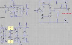
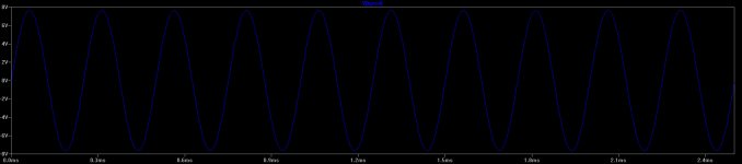
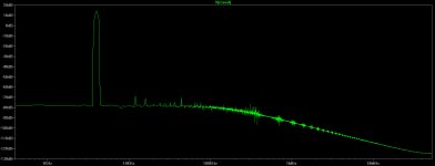
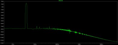
I did some sims in LTSpice to see what gain was the better choise for OPA2134 (well that is how it started). I then implemented the suggested mods and ran transient and FFT. I also added a cap and resistor to the RCA output to see if that would effect the sims, it didn't...but it does help protect amps etc if the BCL is used as a preamp.
Interesting to see that the DC offset is not zero even in simulations.
Now I did this while drinking my morning coffee so there's the chance that I made a mistake somewhere.
Thought the results might be of interest.
Interesting to see that the DC offset is not zero even in simulations.
Now I did this while drinking my morning coffee so there's the chance that I made a mistake somewhere.
Thought the results might be of interest.
Attachments
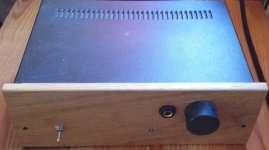
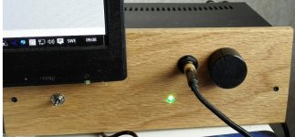
I ran the headamps first real test today.
I had it on for about two hours, fed by a Raspberry Pi 3 running piCoreplayer.
I used a pair of Sony IEM's as I don't want to use my Fidelio X2's yet.
@ 1h45m DC offset was +6.1mVdc/+6.3mVdc measured at the HP jack and with the vol turned all the way down.
Too soon to say anything about SQ, but atleast I consider it stable enough now.
Opamp: OPA2134
Gain: 680R resistor to gnd and 2K2 resistor NC.
This headamp runs hot. I had no problem holding a finger on the heatsinks or any of the caps. But I can see why caps age when using heatsinks connected to the PCB on every heatsource.
In retrospect I'm happy I had to go the weird way I did with heatsinking the transistors. Atleast their heat won't effect how hot the PCB and its components get.
Heat from the Vregs is enough to heat up the caps closest to them. I did use Phobya NanoGrease Extreme thermal compound between those heatsinks and the PCB though. It is a very effective, non-conductive TIM.
I've now been listening for a while to the "mkII" via the Fidelio X2's.
I'm very pleased with the sound. Though much more burn in time is needed.
This headamp and these HP's seem to suit eachother very well.
Using OPA2134, Gain set to +18dB (IIRC, 680R to gnd).
Interconnects are DIY 99.999% 0.6mm silver wire in ptfe, litz-braided.
I know alot of people will frown on that but I like those cables.
Total time the mkII has been playing is less than 10 hours so there's alot more to expect as the headamp settles.
Attachments
- Home
- Amplifiers
- Headphone Systems
- [Headamp] upgrading a Lehmann BCL clone