This Build
Hi All,
I decided to build a stereo prototype because there have been comments about listening to the unit to evaluate several circuits. Additionally there have been at least 2 driver stages proposed. I feel that the only real way for me to listen to this is to construct both channels, at least both driver stages and go from there. It may seem to be more work that necessary for a simple circuit, but I feel it will be worth it in the long run. The build will use buss grounding and the chassis is not intended to carry any more than an incidental ground path to the mains. In very much a similar manner that PC boards are installed, the interchangeable stages will be built on their own platforms. So it should work well for this purpose. Properly rated plugs will be used for the connections. Kinda like one of my machines....
With the various tweaks and such being thrown around I felt it was the best use of my time while you all beat up the details. One thing that I am surprised at is, that for all the knowledge here and the various builds that have been done with this old tube, there exists such variance in the optimal approach. One would have thought, given the age of the tube, that all this would have been explored, developed and finalized. But I don't know enough about this tube thing for that to be an informed observation.
Thanks!
Ron
Member
Joined 2009
Paid Member
Since the days of old a number of things have changed - relative cost of tubes is now much lower, quality of electrolytic caps is massively improved, expected frequency range has expanded to 20 - 20kHz, safety practices, availability of new materials such as metal oxide resistors, np0 ceramic caps, SiC rectifiers. And the bar for overall performance has been raised. But many classic designs are still valid, just look up Asano, Shishido etc.
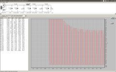
It will be cool when Ron gets this thing breadboarded and ready to do some listening comparisons and actual measurements between changing different component values. I still feel that raising the input filter cap beyond a certain point won't be advantageous, I try and not work the rectifier if I don't have to. I just did all this work between SS, 5AR4, and 5U4GB with a very similar Hammond power transformer and relatively similar loading conditions. Things to remember is the 5AR4 only likes 750mA steady state peak current. A 20uF will disobey this for about 200mS on start up but once the caps charge it will still run at 630mA which is close to it's maximum. So my feelings is that the tube will be stressed at start up and run close to max all the time.
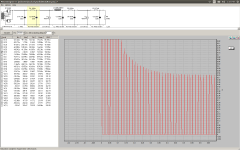
Here is the difference between 20uF and 4.7uF. The 4.7uF doesn't disobey the 750mA draw for more than 100mS which is fine and it levels off at around 520mA. The rectifier will last longer. If you use a 4.7uF and still have to gain voltage you can lower the 220 ohm resistor after the chokes to 100 ohm but I don't think he will have to do that, in fact he might need to lower the value to 2.2uF. Like I said before that if Ron hears or measures a substantial difference with a 20uF by all means use a 20uF but I highly doubt there will be, the B+ ripple is so low with 4.7uF or even 2.2uF already.
Here is the difference between 20uF and 4.7uF. The 4.7uF doesn't disobey the 750mA draw for more than 100mS which is fine and it levels off at around 520mA. The rectifier will last longer. If you use a 4.7uF and still have to gain voltage you can lower the 220 ohm resistor after the chokes to 100 ohm but I don't think he will have to do that, in fact he might need to lower the value to 2.2uF. Like I said before that if Ron hears or measures a substantial difference with a 20uF by all means use a 20uF but I highly doubt there will be, the B+ ripple is so low with 4.7uF or even 2.2uF already.
Attachments
Member
Joined 2009
Paid Member
Layout
Hi,
I have been looking at the 17 width x 12 depth platform that I initially chose for this project, I based it on a measured component size for what I have in house. And it seems a bit tight. I ask, what is the acceptable spacing placement for the components? Transformer to transformer, to choke to choke, tube to tube, etc. Is an inch between enough? Of should there be a greater distance, what is the standard accepted practice here? I don't want anything to be too close. And thanks to you all.
regards,
Ron
It will be cool when Ron gets this thing breadboarded and ready to do some listening comparisons and actual measurements between changing different component values. I still feel that raising the input filter cap beyond a certain point won't be advantageous, I try and not work the rectifier if I don't have to. I just did all this work between SS, 5AR4, and 5U4GB with a very similar Hammond power transformer and relatively similar loading conditions. Things to remember is the 5AR4 only likes 750mA steady state peak current. A 20uF will disobey this for about 200mS on start up but once the caps charge it will still run at 630mA which is close to it's maximum. So my feelings is that the tube will be stressed at start up and run close to max all the time.
Here is the difference between 20uF and 4.7uF. The 4.7uF doesn't disobey the 750mA draw for more than 100mS which is fine and it levels off at around 520mA. The rectifier will last longer. If you use a 4.7uF and still have to gain voltage you can lower the 220 ohm resistor after the chokes to 100 ohm but I don't think he will have to do that, in fact he might need to lower the value to 2.2uF. Like I said before that if Ron hears or measures a substantial difference with a 20uF by all means use a 20uF but I highly doubt there will be, the B+ ripple is so low with 4.7uF or even 2.2uF already.
i agree, except that when i power up and finds that the 2A3 is not at 250v and 60mA bias, that is when i make adjustments...
Member
Joined 2009
Paid Member
I have been looking at the 17 width x 12 depth platform
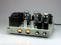
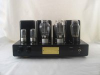
Here's a couple of commercial stereo 2A3 amplifiers you can find for sale on eBay (both less than $1k each) which have a fairly classical layout and chasis design.
The first one is a single Pentode driving a 2A3 and is sized 340W x 230D x 190H (mm)
The second one is a Russian 6SN7 cascade driving a 2A3 and is sized 390 X 320 X 190mm
Attachments
Question
Hi,
I see most of the commercial products have potted chokes on them. What is the difference between them and framed chokes. What will we use in this build and why? If it's a minor cost issue then we will go the best route but is it just appearance?
thanks!
Ron
Hi,
I see most of the commercial products have potted chokes on them. What is the difference between them and framed chokes. What will we use in this build and why? If it's a minor cost issue then we will go the best route but is it just appearance?
thanks!
Ron
I would think that 17" x 12" x 3" should be sufficient. I used 17" x 10" x 3" but I only used one choke. Keep in mind orienting the planes of the transformers by 90 degrees will help reduce electro motive force coupling. Keep hot tubes and resistors far enough away to reduce thermal coupling to capacitors and transformers etc.... Also I hide my chokes underneath so the plane is different, I mount it on the side walls of chassis.
I think Ron ordered some 5k 50watt resistors to load down the B+ taps as he builds the power supply. I think he should be aiming for around 310v at the 2A3 taps, with a 5k load that's 62mA, good enough for testing purposes. 310 because there will be an 11v drop across the output transformer, -45v from the bias voltage at cathode so that should put his 2A3 plate voltage at around 250-255v.
I think Ron ordered some 5k 50watt resistors to load down the B+ taps as he builds the power supply. I think he should be aiming for around 310v at the 2A3 taps, with a 5k load that's 62mA, good enough for testing purposes. 310 because there will be an 11v drop across the output transformer, -45v from the bias voltage at cathode so that should put his 2A3 plate voltage at around 250-255v.
Wire
Hi,
I want to have a good assortment of wire for this project, meaning colours and the proper gages. Do any of you konow where to obtaint a selection of an assortment of the proper gages and the like for this kind of project?
thanks,
Ron
Hi,
I want to have a good assortment of wire for this project, meaning colours and the proper gages. Do any of you konow where to obtaint a selection of an assortment of the proper gages and the like for this kind of project?
thanks,
Ron
fwiw, my recent build had only 4.8volts lost in the opt primary....
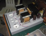
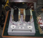
Hi FMB,
You asked me to measure the DCR of the OPTs.
As pictured in the photo there are 4 wires coming from each one.
2 wires are what we will call the upper ones and 2 wires the lower ones.
The resistance was measured across the upper and lower pairs.
Left upper = 1.3, Left lower = 164.7
Right upper = 1.2, Right lower = 156.9
So its Greek to me but there you go for the simulation.
thanks a bunch!
Ron
.06 * 165 = 9.9v
my opt had 80 ohms dc resistance....i have seen OPT's with dc resistances even up to 400+ ohms...
Member
Joined 2009
Paid Member
Hi,
I see most of the commercial products have potted chokes on them. What is the difference between them and framed chokes. What will we use in this build and why? If it's a minor cost issue then we will go the best route but is it just appearance?
thanks!
Ron
I've no idea if potting is really something that adds much in the way of technical performance. I have a Sowter transformer on the shelf for my 2A3 and regard it as a high performance transformer but it is not potted. For those commercial offerings I suspect its mostly about appearance. Since it's your amp you are building you get to choose what you prefer
I've no idea if potting is really something that adds much in the way of technical performance. I have a Sowter transformer on the shelf for my 2A3 and regard it as a high performance transformer but it is not potted. For those commercial offerings I suspect its mostly about appearance. Since it's your amp you are building you get to choose what you prefer
for power traffos yes....i have seen amps humming because of the steel covers, and sometimes even end bells can hum....so aluminum covers can be used instead...in these cases potting helps in order to remove annoyances...
Wow
Hi AJT,
Looks great, nice construction, but as I ask, is there no regular spacing between the transformers and tubes? I measure on my Cary and the ASL that I have and it is at least 1 inch or greater. To All, Should I assume 1.5 inch spacing is good?
thanks,
Ron
Hi AJT,
Looks great, nice construction, but as I ask, is there no regular spacing between the transformers and tubes? I measure on my Cary and the ASL that I have and it is at least 1 inch or greater. To All, Should I assume 1.5 inch spacing is good?
thanks,
Ron
Member
Joined 2009
Paid Member
The only time I remember having trouble with proximity between transformers was with a choke-loaded driver. Even with several inches between the driver choke and the power supply it was not hum free and I included lots of RC filtering into the B+ supply with no improvement. I'm not sure whether the power transformer or the power supply filter chokes were the main source of magnetic leakage but because of this experience I'm very wary of using a choke loaded input stage. Having the OPT transformers fairly close to the power transformer didn't seem to be a problem.
UPS
Hi All,
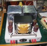
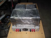
Pieces parts dribbling in.
Pics to follow, working on the aluminum chassis....
Thanks!
Ron
Hi All,
Pieces parts dribbling in.
Pics to follow, working on the aluminum chassis....
Thanks!
Ron
- Status
- Not open for further replies.
- Home
- Amplifiers
- Tubes / Valves
- 2A3 driver