Member
Joined 2009
Paid Member
Ron,
I thought you'd be interested in this article: http://www.pearl-hifi.com/06_Lit_Ar...apers/Loesch_Thorsten/Thorsten_on_SE_Amps.pdf
I thought you'd be interested in this article: http://www.pearl-hifi.com/06_Lit_Ar...apers/Loesch_Thorsten/Thorsten_on_SE_Amps.pdf
Hi,
How's my Team Doing?
Had a couple rough ones, gonna get back on it.
I want to ask about standard wiring conventions. I would expect b+ to be red, maybe it's pair to be ??. Of course 110 black and white, green ground, filament blue, yellow? What is usually done? Or is there not really a standard scheme?
Just want to get it right for you guys to follow and help?
thanks,
Ron
Member
Joined 2009
Paid Member
We're rooting for you Ron - hang in there.
Wires - I usually try to use something obvious like red for B+ and all ground wires in black. The heater wires I try to use whatever is sticking out of the power transformer without adding extensions and the transformer heater wires I've use are often yellow or green.
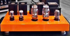
Have you thought about the chasis layout - it can be fun. I like an amplifier to 'look right' with the tubes at the front and transformers at the back - like the example in the attached image (left to right the tubes are input/driver Left, input/driver Right, 2A3 Left, 2A3 Right, and rectifier) although my own amp didn't follow this plan I think my next one will ! You could get a large sheet of paper and make a full scale drawing of the chasis top and then make paper cut-outs for the parts and lay them on top to see how they fit together.
Wires - I usually try to use something obvious like red for B+ and all ground wires in black. The heater wires I try to use whatever is sticking out of the power transformer without adding extensions and the transformer heater wires I've use are often yellow or green.
Have you thought about the chasis layout - it can be fun. I like an amplifier to 'look right' with the tubes at the front and transformers at the back - like the example in the attached image (left to right the tubes are input/driver Left, input/driver Right, 2A3 Left, 2A3 Right, and rectifier) although my own amp didn't follow this plan I think my next one will ! You could get a large sheet of paper and make a full scale drawing of the chasis top and then make paper cut-outs for the parts and lay them on top to see how they fit together.
Attachments
Last edited:
^yellow for anything cathodes, green for grids if needed...
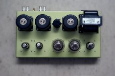
this is how i do my chassis, the Macgyver way....
with masking tapes all around, it is like clamping the box...
this is how i do my chassis, the Macgyver way....
with masking tapes all around, it is like clamping the box...
An externally hosted image should be here but it was not working when we last tested it.
An externally hosted image should be here but it was not working when we last tested it.
this is a 4d32 set that i am working on:
i had boxes made out of BI sheets gage 16 and then powder coated black...
Hi Tony.... We're on the same boat!
Just breadboarded one channel using James 6123 .
Tube line-up is 2C52>6V6>4D32 with 68uf feedback cap.
Very nice sound 😀.
Member
Joined 2009
Paid Member
We already know some of the key parts that Ron plans to use, perhaps we could collectively suggest a practical layout on a suitable off-the-shelf chasis ?
Prototype
Hi Team,
There has been considerable discussion with respect to the driver stage of this amplifier. After all, the thread started with the proposed 2-56 type tubes as the driver. With as many good suggestions that have been made and the design work that has been done I feel that to explore at least several of the options presented it would be best so as to put several things to bed. To that end I am having the tool room guys build a platform that can achieve this. My original desire was to built was about 17 wide by 15 deep, about the size of some of the standard components that I have. The final chassis will be about this size. The OPTs are 5.5x5.5, the 302ax is roughly the same.This gives little room in the width of the component for the final build. Attached photo is about what I want to achieve in the final build. The prototype chassis will be larger by several inches in each direction to accommodate barrier strips in the depth and width so we can easily change caps, resistors on each stage and such during the development. The flow of the amplifier will be counterclockwise starting in the rear right corner ending in the rear left corner where the OPTs are located. The PSU is going to be from the rear right corner to the front right corner.
The driver stage will be in the front center of the unit, with the 2a3s in the front left in front of the OPTs. The current plan is to build 2 driver platforms which can be plugged into the prototype chassis. These platforms will contain all of the components for that stage so it can be swapped with the alternate circuit. I ask you four helpers, if we have a self contained plug in driver circuit, will there be a need to also have a self contained 2a3 board. Or can I consider the PSU once finalized to be static and the power tube circuit static as well. Or will there be component differences in the power tube stage dependent on the driver stage being used? Now is the time for me to know this. basically the initial driver stage being made is a plate with 2 octal sockets and several barrier strips and a breadboard on it. It slides onto the main chassis and electrical connections are made with a "header plug". If the power tube stage needs to be made this way as well, to have a alternate components, now is the time for me to do this. Basically the main chassis is a 20x20 plate that will carry the b+, filament, etc from stage to stage. Should be done by the end of the week. Let me know if the power tube stage need to be interchangeable as well. Whew!
thanks,
Ron
Attachments
Member
Joined 2009
Paid Member
I like the look of that - my thought is that you don't need an interchangeable power tube stage unless you want to try a non-2A3. If you decide on a couple of 'cheap' 2A3 output tubes for testing purposes then the output tube part can be fixed. You might want to try different brand of capacitor for the cathode bypass of the 2A3 however.
Hi,
Exactly my thoughts, if we pick a rectifier and tune the **** out of it's output, then we are done with that end. Then if we tune the power tube stage to what we want to feed the OPTs. Then we can fart around with 2 driver stages. one a single tube, the other the cascade option that has been talked about. Yes I have the cheapo 2a3s for the testing.
Does that sound like a good plan?
thanks!
Ron
Ron,
The censor is a "robot". For the brown, smelly, stuff use $hit. For a rump, butt, etc., use @$$. Damn and blast silly "political correctness". 😀
BTW, I've been known to use guano, frequently. 😉
Your plans have merit.
The censor is a "robot". For the brown, smelly, stuff use $hit. For a rump, butt, etc., use @$$. Damn and blast silly "political correctness". 😀
BTW, I've been known to use guano, frequently. 😉
Your plans have merit.
Last edited:
Hi,
Thanks, it's just the way I would do it if it were a control. The slide ins are connected to the main chassis with Cinch Jones connectors that I have made "buss" type holders out of delrin and will be mounting to the slide ins and the main board.
We will see, it should be interesting.
Thanks Eli,
Ron
Sounds like a great plan!! It is a good idea to always have backup tubes around so the cheap pair of 2A3's for testing is a necessary thing for a tube amp owner regardless.
Hi Ron!
Please do me the favor of measuring the DC resistance of the chokes.
This says it's 195: Hammond Mfg. - D.C. Filter Chokes - (153 - 159 Series)
These say 262: http://www.mouser.com/ds/2/177/5c0032-57977.pdf
158M Hammond Manufacturing | Mouser
Please do me the favor of measuring the DC resistance of the chokes.
This says it's 195: Hammond Mfg. - D.C. Filter Chokes - (153 - 159 Series)
These say 262: http://www.mouser.com/ds/2/177/5c0032-57977.pdf
158M Hammond Manufacturing | Mouser
Member
Joined 2009
Paid Member
I'm still tempted to join you Ron, to maybe see if I can build something similar alongside you.
Joining
Hi,
That would be great, hopefully to put some things to rest and develop a solid platform. I'm still waiting on some items and then can begin.
Thanks,
Ron
Hi,
That would be great, hopefully to put some things to rest and develop a solid platform. I'm still waiting on some items and then can begin.
Thanks,
Ron
- Status
- Not open for further replies.
- Home
- Amplifiers
- Tubes / Valves
- 2A3 driver