I looked through the thread and and can't find Michaels proposed PSU for this amp. If everyone is all for a revised edition of the PSU then I don't mind drawing up other options.
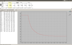
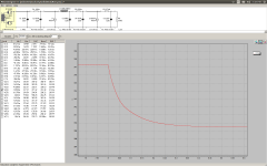
I did a stepped load at 8 seconds on the simulation and as I thought the 20uF gets you zero improvement in regard to transient load. The cool thing about the "pseudo choke input" is that instead of having to swap a bunch of resistors for both channels to increase/decrease voltage one cap will do it 🙂
I did a stepped load at 8 seconds on the simulation and as I thought the 20uF gets you zero improvement in regard to transient load. The cool thing about the "pseudo choke input" is that instead of having to swap a bunch of resistors for both channels to increase/decrease voltage one cap will do it 🙂
Attachments
I looked through the thread and and can't find Michaels proposed PSU for this amp. If everyone is all for a revised edition of the PSU then I don't mind drawing up other options.
I did a stepped load at 8 seconds on the simulation and as I thought the 20uF gets you zero improvement in regard to transient load. The cool thing about the "pseudo choke input" is that instead of having to swap a bunch of resistors for both channels to increase/decrease voltage one cap will do it 🙂
sorry, i failed to get your name right, my bad....
what you have designed is quite good, all i am saying is that anyone building need to be prepared
to change values of resistors to get to the desired operating point of the 2A3....
in my previous builds i used the greatz rectifier and i had the power traffo with several
progressive secondary taps, this enabled me to get to that sweet spot...
sorry, i failed to get your name right, my bad....
Hahaha I looked through the posts a few times thinking I had missed an attachment or something.
hehehe...these tired eyes is failing me.....
you are on the right track, i actually like your approach....
in the VTL stereo 50 that i repaired, they went big time by providing two separate
secondaries of 400vac each... that is extreme and i like it...
of course such traffos are not available to the casual builder,
i just wish traditional winders change their designs...
Preparedness
Hi AJT,
I realize that this is not going to be a 'kit'. I am looking forward to the normal accumulation of the necessary spares that will accompany the development of a device of this complexity. For me, as I am able, this provides a welcome diversion and the excuse to 'get stuff' as well as stumble onto some knowledge under the coaching of some fine folks. No unreal expectations here, just hoping for a good outcome. And as always, thanks for your input.
regards,
Ron
Here is the thing
The spice programs only get you in the ball park and they don't assume real world conditions much of the time. I have seen people build their projects to the exact value of the spice only to have them hum or have excessive distortion afterward. I would never use a small value lytic as a first stage charging cap because even my 1953 Pederson amps which use a 4uf pio in a cap I/P filter wouldn't use a lytic even back then. Your implementation may work but you are coming out of a GZ34 that typically has a minimum of 22uf to 35uf..I'm not saying what your proposing can't work,but it looks like the first cap is an 8uf to 10uf and then goes into 100 ohm resistor and then into a choke..Why not just go for a choke I/P filter and be done with it and then it will regulate as well?.That would make more sense..
The spice programs only get you in the ball park and they don't assume real world conditions much of the time. I have seen people build their projects to the exact value of the spice only to have them hum or have excessive distortion afterward. I would never use a small value lytic as a first stage charging cap because even my 1953 Pederson amps which use a 4uf pio in a cap I/P filter wouldn't use a lytic even back then. Your implementation may work but you are coming out of a GZ34 that typically has a minimum of 22uf to 35uf..I'm not saying what your proposing can't work,but it looks like the first cap is an 8uf to 10uf and then goes into 100 ohm resistor and then into a choke..Why not just go for a choke I/P filter and be done with it and then it will regulate as well?.That would make more sense..
Question
Hi,
To AJT's point- a 302ax is 130.00 USD. Would I be better served by purchasing an additional unit to insure more than adequate power is available ? Meaning dual rectification and double troubles. Or get another transformer altogether with higher available voltages etc, to start with ? We have to nail this down, and as I believe I mentioned, my own thoughts are that a strong, clean PSU is of utmost importance in any build. And I would feel bad if I am wasting anyones time on not starting with a solid foundation simply because I have what the kids picked out.
please advise....
Ron
The spice programs only get you in the ball park and they don't assume real world conditions much of the time. I have seen people build their projects to the exact value of the spice only to have them hum or have excessive distortion afterward.
Spice can't prevent someone from implementing terrible grounding etiquette and or layout design and lead dress. So yes hum is possible with a perfect schematic.
Why not just go for a choke I/P filter and be done with it and then it will regulate as well?.That would make more sense..
Not enough voltage for a choke input filter, and besides load regulation isn't going to help as much as you would think with a class A amplifier, if this was a class A/B or B amp then I would agree.
Intent
Hi michaelsamra!
To catch you up, we are building a complete stereo prototype mockup first. Utilizing barrier strip and development sockets before the actual hard construction. While this will not prove out the elimination of hum due to poor construction techniqes in the final soldered build, it should give us the ability to validate the engineering in the design. And the conveinence of readily swapping out any part(s) we choose. Afer all, I'll only get to do this once, which means I really want all to have as much fun as we can!
thanks for your help!
Ron
Hi AJT,
I realize that this is not going to be a 'kit'. I am looking forward to the normal accumulation of the necessary spares that will accompany the development of a device of this complexity. For me, as I am able, this provides a welcome diversion and the excuse to 'get stuff' as well as stumble onto some knowledge under the coaching of some fine folks. No unreal expectations here, just hoping for a good outcome. And as always, thanks for your input.
regards,
Ron
in my experience, this 2A3 is the easiest to make, and can be hum free as well, so be not afraid to get it right the first time...
Member
Joined 2009
Paid Member
Remember for simple resistor loaded driver stage the psu must not drop B+ too much. For Va of 150V at 10mA we can use Ra of 15k with B+ of 300V.
Spice can't prevent someone from implementing terrible grounding etiquette and or lay
But what caused it was wrong component values in the case of not having adequate filtering and then the excessive distortion in the other amp was caused from too high a value resistor in the concertina phase splitter.
But what caused it was wrong component values in the case of not having adequate filtering and then the excessive distortion in the other amp was caused from too high a value resistor in the concertina phase splitter.
Now it's starting to make sense.
I'm still a little confused on how to follow the threads in this forum but now having a starting point and being able to sub values to tune the circuit,that would be fine..
Hi michaelsamra!
To catch you up, we are building a complete stereo prototype mockup first. Utilizing barrier strip and development sockets before the actual hard construction. While this will not prove out the elimination of hum due to poor construction techniqes in the final soldered build, it should give us the ability to validate the engineering in the design. And the conveinence of readily swapping out any part(s) we choose. Afer all, I'll only get to do this once, which means I really want all to have as much fun as we can!
thanks for your help!
Ron
I'm still a little confused on how to follow the threads in this forum but now having a starting point and being able to sub values to tune the circuit,that would be fine..
another tip, do not use the chassis metal work to run your psu ground returns, use copper wires for that purpose...
I'm still a little confused on how to follow the threads in this forum but now having a starting point and being able to sub values to tune the circuit,that would be fine..
yes, when i build an amp from a schematic, it seldom happened that i do it as drawn, adjustments are made along the way, and with tubes, this is very easy to do and any mistake is usually not catastrophic...
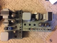
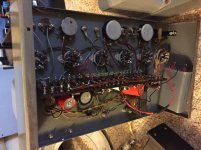
These are Pedersen amps and there is quite a story behind these.
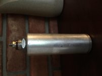
Since we are basically talking so much about power supplies right now,what the hell..Anyway,these came from Charlie Kittelson's estate. When I first got them they actually worked and all original components including the 1st stage oil cap which was 4uf..Anyway I stuck in a 30uf at 600v poly and upon doing that the first choke started buzzing because due to the implementation of this design with two chokes,the 30uf sent the charging current up too high for the size of choke causing it to saturate and therefore buzz. I took it out and put in the 4uf at 600v Vitamin Q and then made the choke happy but what I did do was put in a 35uf poly between the first and second choke and a dual 100uf lytic after that..I'm now going to remove the lytic and go with two more film caps instead for comparison..
These amps have surprisingly large output trafos and I'm talking about 20% larger in size than the T0-300 Acrosounds. They are only 16 watt amps but I was going to wire them in pentode to see how well they would work..Pentode is easier to drive then triode so that won't be a problem..I just want to do this for a test.
Anyway,the reason I mention this is,even tho these amps are just watt triode connected amps,the sound is unbelievably large,dynamic,and pure. This is driving some big NewForm Research ribbons. It shows that power supplies sure make the amp.
Attachments
and the good news is that even newbies can make this amps easily and be rewarded accordingly...
I actually use both unless it's grounded to the return path.
I always use a Buss-Bar but the last set Mc60s I put on some NOS reproduction chassis these made in the late 80s and they looked very pretty but they don't look as original as the ones made now..Anyway one of these old repro chassis there was a tiny piece of chrome off under the fuse holder and what I saw was a copper chassis under the chrome and when I got done these amps the S/N ratio was unbelievably quiet and so I measured it at 1khz on the HP-8903 and it was over 95db..I also verified with the Tektronix 5501 and it was within .5db..I know some of that had to be attributed to that copper chassis.
another tip, do not use the chassis metal work to run your psu ground returns, use copper wires for that purpose...
I always use a Buss-Bar but the last set Mc60s I put on some NOS reproduction chassis these made in the late 80s and they looked very pretty but they don't look as original as the ones made now..Anyway one of these old repro chassis there was a tiny piece of chrome off under the fuse holder and what I saw was a copper chassis under the chrome and when I got done these amps the S/N ratio was unbelievably quiet and so I measured it at 1khz on the HP-8903 and it was over 95db..I also verified with the Tektronix 5501 and it was within .5db..I know some of that had to be attributed to that copper chassis.
Member
Joined 2009
Paid Member
If I had a bit more time I'd be sorely tempted to just join Ron on this venture and build a mock up of the circuit myself - I probably have half the parts already. Nothing like a partner in crime to help the process along. But I wouldn't mock up a stereo version, too much work, just one channel. I'll have to have a root around in my junk box and see what I actually have down in the basement. I know I have some kind of power transformer, a 6C4C and a 2A3 plus a couple of small pentodes.
I always use a Buss-Bar but the last set Mc60s I put on some NOS reproduction chassis these made in the late 80s and they looked very pretty but they don't look as original as the ones made now..Anyway one of these old repro chassis there was a tiny piece of chrome off under the fuse holder and what I saw was a copper chassis under the chrome and when I got done these amps the S/N ratio was unbelievably quiet and so I measured it at 1khz on the HP-8903 and it was over 95db..I also verified with the Tektronix 5501 and it was within .5db..I know some of that had to be attributed to that copper chassis.
yes, that is how i do it, a common ground busbar where all the ground points are soldered together....
- Status
- Not open for further replies.
- Home
- Amplifiers
- Tubes / Valves
- 2A3 driver