Member
Joined 2009
Paid Member
I'm an IBM mainframe CICS system programmer.
Hey! - I worked at IBM Yorktown Heights when I was but a young lad ! (just for a year of Post Doc work) - it's a great company.
IBM
Hi,
Yes Bigun, I agree with the IBM PC (and NASA), they arugably got the entire world where it is in the current mainstream technology today. Not that that is entirely a good thing, I miss the afternoon paper. But all that aside guys, please enumerate the tube sockets I am installing on this prototype build. I have the 4 pins.
Thanks,
Ron
Ok
Hi,
I looked through this thread an it seems octal tubes is what we are working with here. So I will proceed as such, if something should be added please advise.
Did I say somthing wrong?
thanks,
Ron
Hi,
I looked through this thread an it seems octal tubes is what we are working with here. So I will proceed as such, if something should be added please advise.
Did I say somthing wrong?
thanks,
Ron
Member
Joined 2009
Paid Member
Hi Ron,
There is a question of how much playing around you'd like to do - it can be fun but takes more time and effort. You could get yourself a metal chasis and put a range of sockets in it and try all sorts of driver options just for the fun of it. The design approach I proposed is based on the following:
Rectifier: 5AR4 - needs a standard Octal socket
Power tube: 2A3 - needs a good quality 4-pin socket
Driver tubes: those I listed need a standard 9-pin Noval socket and to compare drivers easily I'd install at least two sockets in the experimental chases
If you select a two-stage Cascade of 6SN7 then you'll need a standard Octal socket for that.
The first post of this thread shows my experimental chasis - http://www.diyaudio.com/forums/tubes-valves/280167-yukon-gold-spud-amp.html with several sockets, a volume potentiometer, transformers, mains cable, speaker binding posts, handles, and if you could see underneath it you'd find a number of handy insulated tags inside for mounting wires and resistors to adjacent to the sockets. I used a couple of toggle switches to allow me to switch in and out various resistors and capacitors that I wanted to hear the difference between in real-time (this was super-handy).
I haven't used this supplier before, but it is a recommendation I've received more than once if looking for 'fancy' parts: http://www.percyaudio.com
Last edited:
Remember that I suggested low cost triode wired 6AV5s as "finals", during checkout phases. To correctly load the Hammond power trafo, when 6AV5s are used, connect 1 of these low cost items across each of the 2.5 VAC windings.
Working
Hi All,
Thanks Eli, ordered per your advice. Thanks FMB, ordered as well. Thanks Bigun, all is on the way. Kinda like a holiday. But I'm sure we are going to have fun as we proceed.
Thanks for all your help!
I"ll post when it all gets here. I put together a list pf the components as defined on the PSE design, should I just go ahead and get all that? Or are we goiing to need additional caps, resistors, tubes etc? Let me know and I'll get it ordered.
I have no problem ordering things per your advice, I would just like to not be killed by multiple shipping charges. Unfortunately where I live there is no Layfayette, Heathkit, Radio Shack, or Ham Radio store, (sad). So I have to get ot all online. I realize that we are going to need some extra items going forward so pleaee advise...
Thanks to you all.
Ron
Forget PSE. Your O/P "iron" is for single 2A3s.
Sadly, local stores, for parts, are a thing of the past. As a youngster, I spent a fair amount of time and money at the real Lafayette Radio located at 100 Avenue of the Americas, in Manhattan (NYC). The Canal St. stores had their uses too. All of the above are gone. IIRC, Sylvan/Wellington was the last holdout.
Sadly, local stores, for parts, are a thing of the past.
As a youngster, I spent a fair amount of time and money at the real Lafayette Radio located at 100 Avenue of the Americas, in Manhattan (NYC). The Canal St. stores had their uses too. All of the above are gone. IIRC, Sylvan/Wellington was the last holdout.???
Hi,
Eli, I thought you told me to build the PSE minus the second 2A3 circuit.
Now I am confused....
thanks!
Ron
Hi,
Eli, I thought you told me to build the PSE minus the second 2A3 circuit.
Now I am confused....
thanks!
Ron
PSE = parallel single ended. You can use the cascaded 6SN7 sections small signal circuitry to drive either 1X or 2X 2A3s, as the drive voltage requirement is the same.
Ok
Hi,
So I'm good if I order the parts for the circuit you mention as a start for the driver stage? At least as a start. And the same goes for the first 2A3? Eliminating the parts for the second 2A3. Correct?
thanks,
Ron
Hi,
So I'm good if I order the parts for the circuit you mention as a start for the driver stage? At least as a start. And the same goes for the first 2A3? Eliminating the parts for the second 2A3. Correct?
thanks,
Ron
Hi,
So I'm good if I order the parts for the circuit you mention as a start for the driver stage?
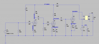
Yes. Check out the attachment. Removing the first stage's cathode bypass cap will lower the gain and distortion of the amp. C5 and C6 don't need to be so large so they get lowered in value.
And the same goes for the first 2A3? Eliminating the parts for the second 2A3. Correct?
Yes you don't want to run parallel 2A3's, all of your transformers will be unhappy unless you plan to bias the 2A3's very cold. So order parts for one 2A3 per channel. And it's not in the schematic but you will want to use another 220 ohm resistor at the grid of the 2A3, you want carbon composition resistors, so that's 6 220R carbon comp resistors.
Attachments
On Track
Hi,
Yes, we all agree that I am using just 1 2A3.
Thank you for the additional part to get.
Now to nail down the PSU parts list.
And I'm working on the prototype breadboard socket holder/ wiring chassis.
Waiting on sockets and stuff, photos when I get it all together for approval.
I might have to get some surgery, so if I disappear for a bit don't abandon me here. Sometimes when you go to see a DR. they just grab you and you are on the table.
Thanks!
Ron
Hi,
Yes, we all agree that I am using just 1 2A3.
Thank you for the additional part to get.
Now to nail down the PSU parts list.
And I'm working on the prototype breadboard socket holder/ wiring chassis.
Waiting on sockets and stuff, photos when I get it all together for approval.
I might have to get some surgery, so if I disappear for a bit don't abandon me here. Sometimes when you go to see a DR. they just grab you and you are on the table.
Thanks!
Ron
GZ34 x1
100R 10 watt x1
Hammond 158M x2
220R 3-5 watt x2
2.7k 1 watt x2
The voltage rating of the capacitors will depend on how safe you want to make it. Basically you can get away with 400v caps but if there was no power tubes in the amp when switched on you could go over the 400v rating, to be completely idiot proof you would want 500v rated caps. The 50uF value is because you can either use two 100uF caps in series rated for 250v and use balance resistors, this gives an equivalent of 50uF 500v, the balance resistors also double as bleed resistors. Or you can buy the easy to mount "can" style caps with multiple sections from JJ or CE Manufacturing, they are already 50uF 500v. Another option is using 400v or 450v caps and they will be easy to find in the more common value of 47uF. You might even find 500v caps in the 47uF value.
2.2uF x1
50uF x5
22uF x2
Also get some 5 watt resistors values ranging from .1 to .47 in case you need to adjust heater voltages. I always try and not run the heater/filament voltages too high to keep tube life as long as possible.
I agree with FMB about sparing filaments. While data sheets frequently allow +- 10%, I'm in favor of not more than 5% on the high side. 10% on the low side is (IMO) OK.
If a decision has not yet been made about the 1st filter cap. in the B+ PSU, I suggest this part. The value of that cap. is well under the limit for the 5AR4/GZ34, while its film dielectric ensures superior performance. FWIW, DC link caps. have been receiving good "press".
If a decision has not yet been made about the 1st filter cap. in the B+ PSU, I suggest this part. The value of that cap. is well under the limit for the 5AR4/GZ34, while its film dielectric ensures superior performance. FWIW, DC link caps. have been receiving good "press".
Raising the 2.2uF value will do two things, raise B+ and stress the rectifier. I don't see him increasing it past 10uF without running into too much B+. As far as datasheets are concerned that max reservoir cap value is to get you close IMHO, basically you can't stick a 60uF cap directly after the rectifier and add an RC filter with low R value and high C value and expect it to be okay. As far as using a film cap there I would not recommend it unless you plan on empirically finding a snubber network for the transformer secondaries. I am under the impression the highish value ESR in electrolytic's helps mitigate the ringing? A snubber network is good but probably overkill with a tube rectifier and electrolytic caps.
I am under the impression the highish value ESR in electrolytic's helps mitigate the ringing?
Top quality 'lytics, like those offered by Panasonic and Nichicon, have remarkably low ESR values. Those parts present a series challenge to film dielectric parts. Touch base with Mike Samra about using film caps. in the 1st position of CLC filters, when vacuum rectifiers are employed.
Where the B+ rail comes in will have to be adjusted at the bench. Of course, the "breadboarded" PSU has to be properly loaded down, including the temporarily idle filament windings. Otherwise, measurements are of little meaning.
I agree, in post #186 I suggest loading the B+ with resistors to make sure voltages are correct, do this also with the filaments loaded.
What I don't understand is the ESR between the 500v 20uF film cap you linked and common electrolytics. I looked at Panasonic and Nichicon caps 22uF 450v and both list loss angle @120Hz .25 and .24. That would put the ESR of them way above the .011 ohm ESR of the film cap.
loss angle = ESR / Xc
Xc of 20uF @ 120Hz = 66
66*.25= 16.5
I will google search this Mike Samra and see what turns up.
Edit: On second glance the film cap datasheets Eli llnked, they are more difficult to read (for me anyway). The loss angle of .28 is at 1kHz and the ESR of .011 ohms is at 10kHz. I am willing to bet someone better at math than I can figure out the numbers for 120Hz, which is what we need to know in order to compare the two caps. My understanding is that even good electrolytics can't compete with film caps.
Last edited:
Member
Joined 2009
Paid Member
I wouldn't waste much money on fancy caps for the first cap after the rectifier - but perhaps somebody can check the ripple current in PSUD, if it's fairly low then the ESR isn't a big concern and even perhaps you don't mind a bit of the benefits of damping from the ESR providing the cap isn't thermally stressed. But the transformer should have a separate snubber across the secondary - this can be added at the final build, it isn't needed right off the bat.
The key is to have a few values on hand in order to find the right value - it'll need to be finalized by trial and error somewhat based on the current draw. And to that end it might be handy to have a dummy load to hang off the B+ rail, some power resistors that will pull down the level of current you'd expect from the amplifier so you can tune up the power supply voltage without the rest of the amplifier being in-play at all.
I still don't like the cascaded two-stage voltage front-end, would suggest single tube. Nevertheless, OP can try it both ways. And I don't like the use of anything other than real 2A3s to stress test the amp and verify the wiring etc. - can't see any value in using something else and not sure why it keeps getting suggested since the OP is willing to spend the $ for low cost 2A3 test mules.
Last edited:
- Status
- Not open for further replies.
- Home
- Amplifiers
- Tubes / Valves
- 2A3 driver