I was talking about the 22p cap, not the 22 ohm R.The 22r shown in post41 is the output device Source resistor.
It sets the bias for the ClassA output stage.
If one assumes the maximum output is 20Vpk, equivalent to 25W into 8ohms, then the bias current should be set to >= 20Vpk/8 = 2.5A
To allow that bias to pass through the combination of mosFET and Source resistor, one would set Rs = 10r and dissipation would be 62.5W. Q1 needs a very big cooler !
A pair of 22r 50W in parallel is equivalent to 11r 100W. That will do the job and allow upto 2.2Apk to the load. Well quite a bit less because a resistor source load allows the stage to generate high 2nd harmonic.
2.2Apk and an 8r0 dummy load is equivalent to 19W from the Buffer.
A 2.5A CCS will allow higher outputs at lower distortions.
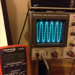
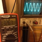
Here some actual screenshots with the amp operating into a 10 ohm resistor.
The amp is as per the amendment original schematic with the 2.2k MOSFET bias resistor replaced with a 2.7k resistor. Frequency is 1kH. Channel 2 is shows.
Pic 1 is befor clipping and is close to 4 watt on the output. Pic 2 is at around 50% before clipping and 1 watt output (no problem for my 99 dB full range speaker).
Attachments
4W and 10r load is equivalent to 894mApk and 8.94Vpk (17.9Vpp)
That shows that you have current clipping @ about 0.9Apk but you have only used 36% of the 50Vdc supply rail.
The amp is set up to work into ~24ohms loads due to the low bias current setting.
If you want to drive loads <<24ohms you need to increase the bias current. Heatsinking will probably become your upper limit before you get to 2.5A of bias current.
To save heat you can reduce your supply voltage. That would allow you to use more of your available voltage swing.
then at the new lower supply voltage you can increase the output bias current.
That then allows a better balance between current clipping and voltage clipping.
Try 40Vdc and 1.5A bias. See if your heatsink is big enough.
Last edited:
4W and 10r load is equivalent to 894mApk and 8.94Vpk (17.9Vpp)
That shows that you have current clipping @ about 0.9Apk but you have only used 36% of the 50Vdc supply rail.
The amp is set up to work into ~24ohms loads due to the low bias current setting.
If you want to drive loads <<24ohms you need to increase the bias current. Heatsinking will probably become your upper limit before you get to 2.5A of bias current.
To save heat you can reduce your supply voltage. That would allow you to use more of your available voltage swing.
then at the new lower supply voltage you can increase the output bias current.
That then allows a better balance between current clipping and voltage clipping.
Try 40Vdc and 1.5A bias. See if your heatsink is big enough.
Thanks Andrew.
I have learnt a lot by following your thought process.
I have upped my bias current to 1.8 amp by reduce the load resistor down to 19 ohm, Vdc is still 50V. I adjusted the bias resistors accordingly and get now closer to 6 Watts output. The heat sink can handle the load.
If I am not mistaken, I have increased my swing usage to 44%.
A long way off. Time is on my side.
Here some actual screenshots with the amp operating into a 10 ohm resistor.
The amp is as per the amendment original schematic with the 2.2k MOSFET bias resistor replaced with a 2.7k resistor. Frequency is 1kH. Channel 2 is shows.
Pic 1 is befor clipping and is close to 4 watt on the output. Pic 2 is at around 50% before clipping and 1 watt output (no problem for my 99 dB full range speaker).
Want to judge distortion on a scope, double the horizontal frequency so you see only two complete sine wave. Your 4W picture doesn't have to clip, it's already heavily distorted. My choke loaded example above running on a 19.5V 6A HP laptop supply, minus 4V for the cap multiplier. The idle current is 1.85A for the SemiSouth JFet and producing close to 10W into 8 Ohm, half of the power consumption what you can achieve with a resistor load. Meaning it is greener and needs less heatsinking. The distortion is much better what one can get out of a class A tube output stage, and the bandwidth is around 250kHz with those cheap Hammond chokes. Almost unbeatable combination for a small room, with a good quality bookshelf spkr + a sub.
Thanks MiklosWant to judge distortion on a scope, double the horizontal frequency so you see only two complete sine wave. Your 4W picture doesn't have to clip, it's already heavily distorted. My choke loaded example above running on a 19.5V 6A HP laptop supply, minus 4V for the cap multiplier. The idle current is 1.85A for the SemiSouth JFet and producing close to 10W into 8 Ohm, half of the power consumption what you can achieve with a resistor load. Meaning it is greener and needs less heatsinking. The distortion is much better what one can get out of a class A tube output stage, and the bandwidth is around 250kHz with those cheap Hammond chokes. Almost unbeatable combination for a small room, with a good quality bookshelf spkr + a sub.
That is an interesting looking amplifier of yours. And thanks for the tip with the scope.
Want to judge distortion on a scope, double the horizontal frequency so you see only two complete sine wave. Your 4W picture doesn't have to clip, it's already heavily distorted. My choke loaded example above running on a 19.5V 6A HP laptop supply, minus 4V for the cap multiplier. The idle current is 1.85A for the SemiSouth JFet and producing close to 10W into 8 Ohm, half of the power consumption what you can achieve with a resistor load. Meaning it is greener and needs less heatsinking. The distortion is much better what one can get out of a class A tube output stage, and the bandwidth is around 250kHz with those cheap Hammond chokes. Almost unbeatable combination for a small room, with a good quality bookshelf spkr + a sub.
I guess I am not understanding this but are the Hammond chokes being used as the resistive load for the bias current?
Being able to run from a laptop SMPS for class A is very nice can you share the schematic?
I guess I am not understanding this but are the Hammond chokes being used as the resistive load for the bias current?
Being able to run from a laptop SMPS for class A is very nice can you share the schematic?
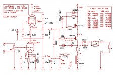
The DC choke has very low DC resistance, so the power dissipated on it is low.
The schematic shows an earlier version of the same principle.
It has a bigger choke ,uses the Sony 2SK82 VFet and the Russian version of the ECL84 triode/pentode Mu stage as the driver. Either the HMN or this MU stage would be able to drive the inexpensive IRF240 MOS Fet to. Both can deliver up to 10V clean signal for the output Fet. The 0.1 Ohm series with the choke is for to measure the idle current.
Attachments
That's a nice circuit. I can't find anything on the 2SK82 (not 83 and current way too low as it is TO92).
Currently more than one project is going on Diyaudio with it, one of them from Nelson Pass.
Google sk82 or vfet, an obsolete Sony VFet, but you can use the IRF240 instead. Eventually you also could use the 2SJ18, with opposite polarity on the power and bias supply, but it has lower power rating.
Google sk82 or vfet, an obsolete Sony VFet, but you can use the IRF240 instead. Eventually you also could use the 2SJ18, with opposite polarity on the power and bias supply, but it has lower power rating.
G'day Glossmaster, I really like your amp. I normally stay away for tube stuff because its HV involved. Yours looks so simple and doesn't involve lethal voltage, even NOOBs like me could have a good chance of building it successfully. If I understand it correctly, you're using only half of 6922 for each channel, that means 1 6922 is good for a stereo amp, am I right? sorry for the NOOB question.
G'day Glossmaster, I really like your amp. I normally stay away for tube stuff because its HV involved. Yours looks so simple and doesn't involve lethal voltage, even NOOBs like me could have a good chance of building it successfully. If I understand it correctly, you're using only half of 6922 for each channel, that means 1 6922 is good for a stereo amp, am I right? sorry for the NOOB question.
Hello EBB.
Yes, I wanted this to be a low voltage tube driven Hybrid amplifier of the simplest possible kind. One could easily just leave it as is and enjoy listening to it. You would not have to worry about mega big heat sinks if you can put up with low power out put.
On the other hand, if you build the circuit onto a bread board, it is easy to change values or add a bit more complexity as DIY members add some of their snippets of wisdom.
All the time learning something new as you go along, I know I do. Like your self, I am still very green on the subject.
And yes, I use the tube stereo. L and R channel in one tube.
The most expensive part is the power supply and the heat sink(s)
I took the bread board into the living room again the other day and listen to music for about three hours until the wife came home and I had to stop.😉
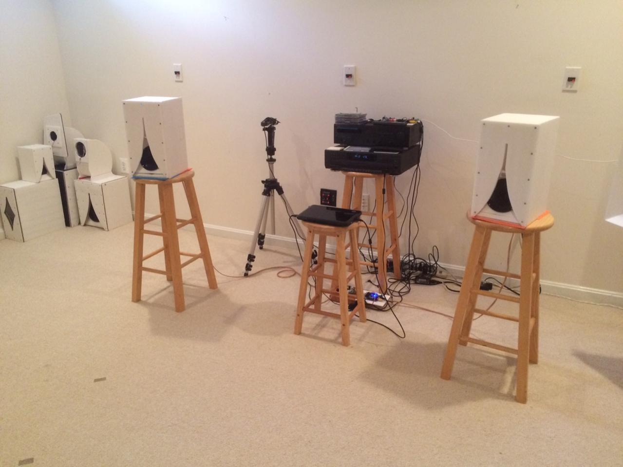
Glossmaster is right - once you have a power supply and heat sink the rest is pretty low cost. One thing I have discovered is that my relatively low cost class AB heatsink ($5ea) can easily be upgraded to class A duty by addition of a quiet 50mm 12v brushless fan ($1) and a 7812 regulator or other source of 100mA 12v. Heatsink barely gets warm with 30w and I expect can handle 60w no problem.
I have a 300VA 32v toroidal transformer that I need to make a PSU board for. With 125vac mains I expect it can make 48 to 49vdc. That transformer was $50 and the most expensive part. However can be used for many other amp projects once you have one.
Here is the heatsink and fan cooling a 5W ACA class A amp.
Last edited:
Glossmaster is right - once you have a power supply and heat sink the rest is pretty low cost. One thing I have discovered is that my relatively low cost class AB heatsink ($5ea) can easily be upgraded to class A duty by addition of a quiet 50mm 12v brushless fan ($1) and a 7812 regulator or other source of 100mA 12v. Heatsink barely gets warm with 30w and I expect can handle 60w no problem.
I have a 300VA 32v toroidal transformer that I need to make a PSU board for. With 125vac mains I expect it can make 48 to 49vdc. That transformer was $50 and the most expensive part. However can be used for many other amp projects once you have one.
Here is the heatsink and fan cooling a 5W ACA class A amp.
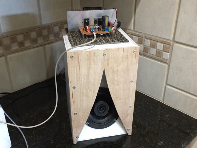
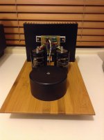
Same for me, this 20W Class A mono block runs at 75C without extra cooling like in this picture. I made provisions to plug in a 24Vdc fan and with that strapped to it it stays at a balmy 45C. Work in progress.
XRK971 I have seen that speaker design somewhere. This looks like a miniature version.
Attachments
Glossmaster,
Nice amp you have there. I like bamboo cutting board as main structure. Which 20W class A design is that?
The speaker shown is a variant of the Karlson speaker. The original Karlson from 1955 was a large 15in driver speaker. The topology had excellent efficiency dynamics and dispersion thanks to Karlson aperture acoustic lens.
The one show above is my take on scaling such a speaker down. Simply scaling a K15 down to a 5in driver has no bass. So I came up with the XKi - a 6th order band pass with K aperture. I am using a custom modified PA130-8 with coaxial tweeter. More info on XKi here:
http://www.diyaudio.com/forums/full-range/268524-xki-xs-ab-initio-karlson-6th-order-bandpass.html
There are also the Karlsonstor variants that sound very good. Excellent for use with high sensitivity full range speakers. The K'nator is one of the few speakers with so much bass gain that you do not need baffle step compensation. The bass output matches the mud and highs rated at 1kHz.
More on K'nator here:
http://www.diyaudio.com/forums/full-range/239338-mini-karlsonator-0-53x-dual-tc9fds.html
Karlsons sound very nice and at one point Inhad a room full of them 🙂
Last edited:
Glossmaster,
Nice amp you have there. I like bamboo cutting board as main structure. Which 20W class A design is that?
Krk971 this is the amp design. I have a bit of an issue with it. it looks terrible on the scope but you would not know if you listen to it. I think the pcb design lets it down. It was my first attempt and I did not put any thought into proper lay out practice. Might redesign the pcb or get a pass F5 board and run that. Supply is +/- 22vdc so should just fit nicely.
20 Watt Class-A Amplifier
That looks really interesting. Could a 2SC5200 be used instead of the MJE2955? I have a bunch of them. I think I have all the other parts too. I am not sure if a PCB layout is the issue - it may be that a resistor as a constant current source or sink for the LTP is not linear enough. Use a simple LTP pair with like transistor for the sink from a circuit I am familiar with such as the Apex series of amps that use a BC546 like this may just work.
An externally hosted image should be here but it was not working when we last tested it.
I could not open your link xrk971.That looks really interesting. Could a 2SC5200 be used instead of the MJE2955? I have a bunch of them. I think I have all the other parts too. I am not sure if a PCB layout is the issue - it may be that a resistor as a constant current source or sink for the LTP is not linear enough. Use a simple LTP pair with like transistor for the sink from a circuit I am familiar with such as the Apex series of amps that use a BC546 like this may just work.
An externally hosted image should be here but it was not working when we last tested it.
I used TIP2955 for my 20W Class A amp.
The only big issue I could see between the 2SC5200 and the MJE/TIP 2955, is the PNP/NPN difference.
Once I am done with the project at hand I will build the circuit again on the bread board and play around with it.
I could not open your link xrk971.
I used TIP2955 for my 20W Class A amp.
The only big issue I could see between the 2SC5200 and the MJE/TIP 2955, is the PNP/NPN difference.
Once I am done with the project at hand I will build the circuit again on the bread board and play around with it.
I have the 2SA1943 also, I thought the 2wC5200 matchd the MJE2955. Which link does not open?
Hello EBB.
Yes, I wanted this to be a low voltage tube driven Hybrid amplifier of the simplest possible kind. One could easily just leave it as is and enjoy listening to it. You would not have to worry about mega big heat sinks if you can put up with low power out put.
On the other hand, if you build the circuit onto a bread board, it is easy to change values or add a bit more complexity as DIY members add some of their snippets of wisdom.
All the time learning something new as you go along, I know I do. Like your self, I am still very green on the subject.
And yes, I use the tube stereo. L and R channel in one tube.
The most expensive part is the power supply and the heat sink(s)
I took the bread board into the living room again the other day and listen to music for about three hours until the wife came home and I had to stop.😉
Glossmaster is right - once you have a power supply and heat sink the rest is pretty low cost. One thing I have discovered is that my relatively low cost class AB heatsink ($5ea) can easily be upgraded to class A duty by addition of a quiet 50mm 12v brushless fan ($1) and a 7812 regulator or other source of 100mA 12v. Heatsink barely gets warm with 30w and I expect can handle 60w no problem.
I have a 300VA 32v toroidal transformer that I need to make a PSU board for. With 125vac mains I expect it can make 48 to 49vdc. That transformer was $50 and the most expensive part. However can be used for many other amp projects once you have one.
Here is the heatsink and fan cooling a 5W ACA class A amp.
I have a stack of big heatsinks 300x151.5x40mm I got from my local manufacturer for the cost of peanuts. I also have a few 300VA 2x25V toros as well, but I don't think they are suitable for the Hybrid unless I connect 2 secondaries in series and regulate it down to about 50V. I have yet to figure out how to do that though. Or I might save it for another project such as Rod's Class A amp you guys are talking about, it's also simple enough to build it as dead bug. Hmm just too many temptations and too many concurrent projects.😀
Last edited:
- Status
- Not open for further replies.
- Home
- Amplifiers
- Solid State
- Simple Class A Hybrid MOSFET Source Follower