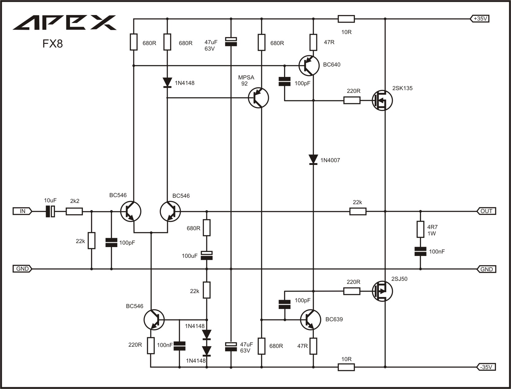
That looks really interesting. Could a 2SC5200 be used instead of the MJE2955? I have a bunch of them. I think I have all the other parts too. I am not sure if a PCB layout is the issue - it may be that a resistor as a constant current source or sink for the LTP is not linear enough. Use a simple LTP pair with like transistor for the sink from a circuit I am familiar with such as the Apex series of amps that use a BC546 like this may just work.
An externally hosted image should be here but it was not working when we last tested it.
The image link.
The 2SA1934 beeing a PNP should fit straight in I would think.
Last edited:
Output stage biasing on this one leaves a lot to be desired though...
(schematic reproduced for clarity)
Interesting circuit, I would recommend considering a bootstrapped cascode though. Output FET capacitance is already reduced by the regular cascode, but input stage quiescent current still isn't very much to write home about, so further reduction would certainly be appreciated in the interest of high-frequency distortion.
I'd also consider going for a gyrator or adjustable current source instead of the choke. 80 mH @ 2 A (comfortably) doesn't sound cheap or small.
(Note that DC-offset heating is probably to be recommend for the ECL84 in order to get the voltage between cathode and heater down and avoid long-term damage.)
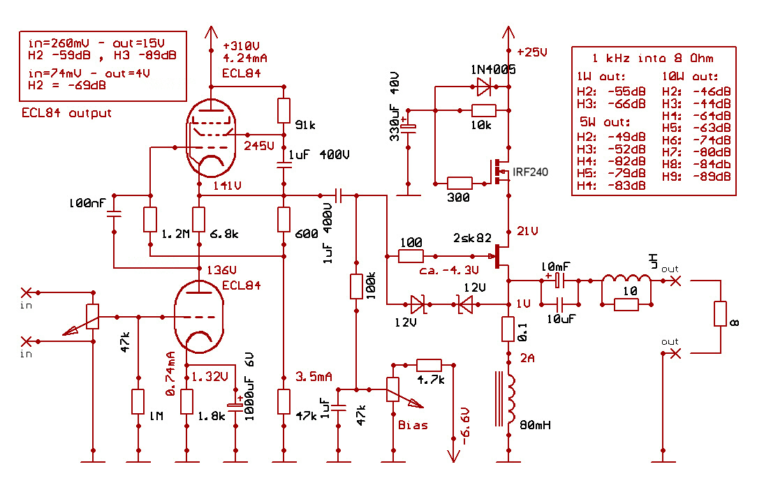
The schematic shows an earlier version of the same principle.
It has a bigger choke ,uses the Sony 2SK82 VFet and the Russian version of the ECL84 triode/pentode Mu stage as the driver. Either the HMN or this MU stage would be able to drive the inexpensive IRF240 MOS Fet to. Both can deliver up to 10V clean signal for the output Fet. The 0.1 Ohm series with the choke is for to measure the idle current.
(schematic reproduced for clarity)
Interesting circuit, I would recommend considering a bootstrapped cascode though. Output FET capacitance is already reduced by the regular cascode, but input stage quiescent current still isn't very much to write home about, so further reduction would certainly be appreciated in the interest of high-frequency distortion.
I'd also consider going for a gyrator or adjustable current source instead of the choke. 80 mH @ 2 A (comfortably) doesn't sound cheap or small.
(Note that DC-offset heating is probably to be recommend for the ECL84 in order to get the voltage between cathode and heater down and avoid long-term damage.)
Last edited:
Not sure what happened try this link
I see what you are saying, it looks like a straight forward implementation.
It looks like it might provide better balance all together.
I am in the process of beefing up my power supply for the Hybrid. I increased the bias current to 2.5 Amp as suggested by Andrew T. I paralleled two 27R 50W resistors for a 13.3 load but the 5 A draw for the two channels is a bit much on the current setup. Lucky I have a bigger transformer in my draw.
Last edited:
5 A draw for the two channels
That's a lot of heat. 🙂
The BC546 LTP and CC sink in the FX8 amp above works very well as the amp sounds excellent and is very simple. Although this is kind of OT as it is related to the 20w class A amp you posted earlier and not the subject of this thread.
Although... one could use the FX8 front end with a suitable driver (like BD139/140) to power the IRF240 in a SE class A. I might give this a go in a TINA sim and see what happens.
5A of current draw for the two channels requires a massive transformer.
The absolute minimum is one rated @ 10Aac, but his ends up running the transformer at maximum rated output and it will run hot.
I suggest you use a transformer rated at 20Aac for a 5Adc continuous current draw.
The absolute minimum is one rated @ 10Aac, but his ends up running the transformer at maximum rated output and it will run hot.
I suggest you use a transformer rated at 20Aac for a 5Adc continuous current draw.
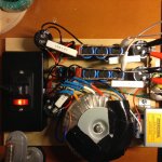
Beefed up power supply ready.
Rail is at 43Vdc, bias current 2A, load resistor is now 13R, power out 6w measured against a 10R resistor.
Base has segnificantly increased to a point where I replaced the output cap to 1000uF down from 4700nF to suit my ZU's.
I might look into implementing a 200V supply for the tube to get it to operate In a more linear region.
Attachments
Nice power supply. I am still waiting for tube bases to arrive. I fear they too are coming from overseas even though ordered on Amazon.
Nice power supply. I am still waiting for tube bases to arrive. I fear they too are coming from overseas even though ordered on Amazon.
That would be about right. Probably would cost them 2 cents more sourcing it from the US.
Funny thing is, here in Western Australia it is sometimes quicker ordering parts from the US and get them delivered than getting them from Eastern Australia.
By the way I got my self some of these to try.
http://www.farnell.com/datasheets/866120.pdf
They have a very low input capacitance.
Output stage biasing on this one leaves a lot to be desired though...
(schematic reproduced for clarity)
Interesting circuit, I would recommend considering a bootstrapped cascode though. Output FET capacitance is already reduced by the regular cascode, but input stage quiescent current still isn't very much to write home about, so further reduction would certainly be appreciated in the interest of high-frequency distortion.
I'd also consider going for a gyrator or adjustable current source instead of the choke. 80 mH @ 2 A (comfortably) doesn't sound cheap or small.
(Note that DC-offset heating is probably to be recommend for the ECL84 in order to get the voltage between cathode and heater down and avoid long-term damage.)
Thank you for your assessment of the amp.
Maybe you could tell me what's wrong with the biasing, it's a filtered, regulated 6.6V supply. The noise on it will appear on the speaker terminal, but it has minimal noise. After power on ,it has to come up faster than the main Low voltage B+.
I'm using the robust 6F4P ,the Russian version of the ECL84. The 6F4P tube pentode section is a CRT driver and can take -150 to +200V between the cathode and the filament. I have built a few of these Mu stages with this tube trough the years and non of them failed yet.
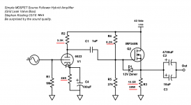
I made two identical housing, one which used for this amp, the other for one which using the SemiSouth power jFet and the half HMN as a driver.
The HMN has lower output impedance and wider bandwidth, but a bit more complicated to build. The advantage is that uses 165V for the high voltage supply, while the 6F4P 320V. The 1W -1dB poit for this 6F4P/SK82 amp is 112kHz.
The price of the chokes , especially the 60mH 2A Hammond one is not much, and since I building it for my self , not for sale, I can take it.
Member
Joined 2009
Paid Member
I love it.
The choke, why do you need the 0.1R in series - is there not enough DCR in the choke ?
Did you try/consider LED bias for the lower triode instead of traditional RC ?
The choke, why do you need the 0.1R in series - is there not enough DCR in the choke ?
Did you try/consider LED bias for the lower triode instead of traditional RC ?
I love it.
The choke, why do you need the 0.1R in series - is there not enough DCR in the choke ?
Did you try/consider LED bias for the lower triode instead of traditional RC ?
Thanks Bigun.
The 0.1 Ohm is just for the easy measurement of the idle current.
Yes, I considered it, but never got around it in this amp.
I built one i/v amp, for a CD player with red LED in the triode catode and it's working well.
Glossmaster,
You have made several changes to the circuit since Post 1. Do you have a final circuit you would recommend that I go with now? Can you point me to the latest schematic or upload one if it hasn't been done already?
Thansk,
X
my tube sockets came today. 🙂 My 50v PSU board came to0...
You have made several changes to the circuit since Post 1. Do you have a final circuit you would recommend that I go with now? Can you point me to the latest schematic or upload one if it hasn't been done already?
Thansk,
X
my tube sockets came today. 🙂 My 50v PSU board came to0...
Glossmaster,
You have made several changes to the circuit since Post 1. Do you have a final circuit you would recommend that I go with now? Can you point me to the latest schematic or upload one if it hasn't been done already?
Thansk,
X
my tube sockets came today. 🙂 My 50v PSU board came to0...
Oh nice, I look forward to what you will make of this.
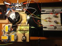
Here is my last update. I paralleled two 50W R27 resistors as a load. I had the bias current at 2 A at one stage but for the sake of the heat generated dropped it back to 1.6 A.
I have been playing around with different bias resistor ratios a bit.
And last but not least for the sake of linearity I just finished implementing a HT supply for the tube (164V on the Plate).
I look forward to your opinion on the low voltage version.
Attachments
It's going to take me a few days to absorb all of this and then implement in a point-to-point circuit. I have a brand new toroid trafo for the PS and brand new PSU board so will need to test those first to make sure all is good before employing them here. Also wondering if I can use a simple wall wart AC transformer used by small electronics as the fillament heater source? Or I need to whip up an LM317 VR to generate 6.8vdc. Can DC work for the filament or is there some magic to having an AC for the filament heater for it to work? Also need to figure out how to heat sink the sand cast resistors as I know they can get smoking hot. I had a 25w 10ohm one the other day get 25v across it for a few minutes and I accidentally touched - it's like touching the tip of a soldering iron. 🙁
I am also wondering if using a constant current source like what is done with ACA amp using another IRFP240 - rather than the bank of resistors. It will give lower distortion I think and is not that complicated to implement. 3 resistors, a cap, a small TO92 NPN (probably a MPSA42 can work) and another IRFP240.
Simple resistor bank first, and do the CCS later. I have qnty 10 x 10ohm 10watt resistors so should be able to dial almost anything. Maybe parallel two 40ohm strings for 20ohms at 80w total capacity?
Also wondering if I can use a simple wall wart AC transformer used by small electronics as the fillament heater source? Or I need to whip up an LM317 VR to generate 6.8vdc. Can DC work for the filament or is there some magic to having an AC for the filament heater for it to work? Also need to figure out how to heat sink the sand cast resistors as I know they can get smoking hot. I had a 25w 10ohm one the other day get 25v across it for a few minutes and I accidentally touched - it's like touching the tip of a soldering iron. 🙁
Hehe, no AC magic happening here. It is just a matter of simplicity. I had a transformer with a 6.3V tap handy, as simple as that. You can use a wall wart without a problem. DC is not really required. There are actually builders that only use AC on the driver's filament. Some say DC flattens the dynamics.
I used 5 100R 10W in parallel as a source resistor before I got my hands on the 27R 50W and messured them to be 130C with 2.4A of current running through them.
I would not mind trying to implement a ccs and will probably play around with it in due course. You will likely beat my to it.
By the way I hooked up the bread board to my ZU's with the HT supply in place for the 6922.
😱
Oh my! Well worth the 35$ for the parts.
- Status
- Not open for further replies.
- Home
- Amplifiers
- Solid State
- Simple Class A Hybrid MOSFET Source Follower