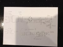
XRK971 if you get your bits, just check out my revised schematics.
The value of some of the resisters has changed. I have added a cathode resistor (68 Ohm) and I have changed the plate resistor to 3.3K Ohm. This improved the sine wave and increased the gain.
When I load tested the amp, I found the bias needed a bit of tweaking to center the sine wave. So R4 is now 2.2K Ohm.
The output is now just under 4W on the onset of clipping.
These values are for a 50Vdc supply on the rail.
I did run it with a pre amp just for the sake of it, but it is not really needed. That is what your 6922 is for.
Ok, I think I have most of my parts and I need to verify if I can use 50v electrolytics here. Can the output 4700uF by lower voltage like 35v even or does that need to be 50v as well? Can all regular resistors be 1/8 watt and only power resistor is high power?
I plan to use a marker to draw the traces on copper PCB and hand etch this one as my first hand made PCB.
Btw, I recently found that the 53v Abletec SMPS with a CRCLC filter gets me 1mV ripple when used with a 90w class AB amp. I wonder if I can use it here or fact that this is class A will need a 49v rail 300va trafo.
What is the typical bias current through MOSFET?
Last edited:
Ok, I think I have most of my parts and I need to verify if I can use 50v electrolytics here. Can the output 4700uF by lower voltage like 35v even or does that need to be 50v as well? Can all regular resistors be 1/8 watt and only power resistor is high power?
What is the typical bias current through MOSFET?
I would use a 50V part as minimum, if for some reason the mosfet shorts to the rail it will take out the cap and possibly damage the speaker. The idle current will always be determined by the voltage at the source and the load resistor value. Based on the last schem posted, it's about 29 volts @2.15A.
Last edited:
Btw, I recently found that the 53v Abletec SMPS with a CRCLC filter gets me 1mV ripple when used with a 90w class AB amp. I wonder if I can use it here or fact that this is class A will need a 49v rail 300va trafo.
What is the typical bias current through MOSFET?
You can easily work out your current draw if you know what bias current you will settle for. The Tube will only draw around 3mA so you can take that out of the equation.
Any way, I dropped the ball a bit on the project. I am very busy at work plus I am in the process of designing an integrated valve amp from the ground up for a valve amp building camp I will host in the near future. This takes up all my time.
The Hybrid is still on the bread board and I listen to it when I work on the valve amp project. I still enjoy the sound it puts out. (Remember the 6922 is know on B+290V )
Is there a huge improvement in SQ with 290v B+ vs 50v B+? Does that give higher gain for the "preamp"?
I am thinking I need those aluminum cases power resistors so that I can mount them to a fan cooled heatsink. I don't want to go with lightbulbs but trying to keep this compact. The resistor bank can come in handy as a dummy load for amp testing.
I am thinking I need those aluminum cases power resistors so that I can mount them to a fan cooled heatsink. I don't want to go with lightbulbs but trying to keep this compact. The resistor bank can come in handy as a dummy load for amp testing.
I you look at the anode characteristics of the 6922 you will see that to run the tube in the most linear region you really need a HT supply. The difference is well worth the effort. And if you use a back to back transformer in the US you can use a voltage doubler to get roughly 330V on the HT which is taken into consideration when drawing the load lines.Is there a huge improvement in SQ with 290v B+ vs 50v B+? Does that give higher gain for the "preamp"?
I am thinking I need those aluminum cases power resistors so that I can mount them to a fan cooled heatsink. I don't want to go with lightbulbs but trying to keep this compact. The resistor bank can come in handy as a dummy load for amp testing.
Filtering should be cost effective with a CRC using 400V caps or 200V in series if cheaper.
You could t off low voltage for your filament supply between the back to back transformers if you like. 1 A supply is all you need.
I plan on building the high voltage version (330V B+)of this amp during the coming weekend as I am seriously piqued by the potential of this hybrid amp (and just so happen to have the needed components in my parts bin)
Could anyone advise on a schematic with 1.8A bias for the IRF and 330V B+ for the 6922?
Could anyone advise on a schematic with 1.8A bias for the IRF and 330V B+ for the 6922?
I you look at the anode characteristics of the 6922 you will see that to run the tube in the most linear region you really need a HT supply. The difference is well worth the effort. And if you use a back to back transformer in the US you can use a voltage doubler to get roughly 330V on the HT which is taken into consideration when drawing the load lines.
Filtering should be cost effective with a CRC using 400V caps or 200V in series if cheaper.
You could t off low voltage for your filament supply between the back to back transformers if you like. 1 A supply is all you need.
Can you give a rough diagram of the 330v supply? When you say back to back transformer and a doubler do you mean two 58v transformers with outputs in center tap series to get 115, then voltage double to 230v x 1.41= 324v? I have a bunch of 450v mkt 10uF caps. Also several motor start 50uF 450v caps. How many uF's needed and what R value to use in CRC? Would 60uF and 2.2k and 60uF as a filter give me enough current? The B+ doesn't use much current I assume as it's a plate voltage.
I did not use a doubler as we have 240v here down under. I used just back to back transformers and presto,330VDC rectified.
You might have to use a capacitor doubler like on the drawing. Do not fit the resistors parallel to the caps. Values are flexible, except for the voltage.
Resistor values for the tube work for my setup. I forgot to include the cathode bypass capacitor. (470uF 62v)
You might have to use a capacitor doubler like on the drawing. Do not fit the resistors parallel to the caps. Values are flexible, except for the voltage.
Resistor values for the tube work for my setup. I forgot to include the cathode bypass capacitor. (470uF 62v)
Attachments
Did you actually get 330Vdc from your two back to back transformers.
A 230:12Vac transformer is probably close to a 17.7:1 Turns Ratio, allowing for ~8% regulation.
What was the mains voltage to get your desired output voltage?
A 230:12Vac transformer is probably close to a 17.7:1 Turns Ratio, allowing for ~8% regulation.
What was the mains voltage to get your desired output voltage?
I am not sure what the purpose of the back to back trafo is? You end up with 1:1, why not just use straight line voltage from wall to a doubler?
As far as I know, a back to back trafo configuration should take care of any high frequency content on the power lines.
I don't know if this is necessary here though...
I don't know if this is necessary here though...
from the forum rules:
"While most projects on this site deal with electricity and construction which inherently involve some risk, particularly dangerous topics and procedures should include a warning in the thread that adequately explains these risks. Certain inherently dangerous topics are not allowed. At this time they include but are not limited to: discussing power supplies directly fed by mains current without a transformer"
"While most projects on this site deal with electricity and construction which inherently involve some risk, particularly dangerous topics and procedures should include a warning in the thread that adequately explains these risks. Certain inherently dangerous topics are not allowed. At this time they include but are not limited to: discussing power supplies directly fed by mains current without a transformer"
You don't get 1:1 using back to back transformers.I am not sure what the purpose of the back to back trafo is? You end up with 1:1, why not just use straight line voltage from wall to a doubler?
that's why I asked what input volktage he used and whether he achieved his required 330Vdc.
a 230:12 8% regualtion transformer has an open circuit output of 12* 1.08 Vac Therefore the output voltage is 12.96Vac. The Turns Ratio is 17.747:1
Now put in a back to back and the output voltage with no load on either transformer will be 230Vac input gives 230Vac output.
But load up the transformers and the output will drop to ~197Vac
If one uses 245Vac as the input instead of 230Vac one gets a loaded output of ~210Vac. That would give well short of 330Vac, maybe as low as 296Vac.
from the forum rules:
"While most projects on this site deal with electricity and construction which inherently involve some risk, particularly dangerous topics and procedures should include a warning in the thread that adequately explains these risks. Certain inherently dangerous topics are not allowed. At this time they include but are not limited to: discussing power supplies directly fed by mains current without a transformer"
Ahhh... safety. Let's have a transformer step up mains to 1200v - but yes, it's isolated from the mains by a transformer so should be "safer".
What about something like this boost converter for $8? Put some good RCRC filtering behind it.
High Voltage DC DC Boost Converter input 3V 5V Step up to output 200V 620V 300V 350V adjustable Power PSU Module-in Integrated Circuits from Electronic Components & Supplies on Aliexpress.com | Alibaba Group
You don't get 1:1 using back to back transformers.
that's why I asked what input volktage he used and whether he achieved his required 330Vdc.
a 230:12 8% regualtion transformer has an open circuit output of 12* 1.08 Vac Therefore the output voltage is 12.96Vac. The Turns Ratio is 17.747:1
Now put in a back to back and the output voltage with no load on either transformer will be 230Vac input gives 230Vac output.
But load up the transformers and the output will drop to ~197Vac
If one uses 245Vac as the input instead of 230Vac one gets a loaded output of ~210Vac. That would give well short of 330Vac, maybe as low as 296Vac.
The Back to back transformer is for safety. I was not keen on using the 240V out of the socket without isolation..
The B+ when loaded, is 294Vdc, this is plenty for a 6922 as the max Plate voltage is 300Vdc. An avarage plate current of 15mA per side is easily achieved.
Nothing wrong with using two isolating transformers.
It is Xrk that got it wrong by saying 1:1
And your new info stating 294Vdc from the back to back transformers confirms that the two regulation values need to be taken into account.
It is Xrk that got it wrong by saying 1:1
And your new info stating 294Vdc from the back to back transformers confirms that the two regulation values need to be taken into account.
Don't they make 1:1 isolation transformers for line level output? What do you think of the step up switcher unit?
And what if one uses an 18vac step down connected back to back with 20vac step up - would this offset the regulation losses? These are $10 ea for a 10VA trafo.
http://www.antekinc.com/an-0118-10va-18v-transformer/
http://www.antekinc.com/an-0120-10va-20v-transformer/
And what if one uses an 18vac step down connected back to back with 20vac step up - would this offset the regulation losses? These are $10 ea for a 10VA trafo.
http://www.antekinc.com/an-0118-10va-18v-transformer/
http://www.antekinc.com/an-0120-10va-20v-transformer/
Last edited:
Does that lower the final output voltage?
You need a higher turns ratio in the second transformer, i.e. 18:260Vac. But that becomes a special at considerably extra cost.
The idea of a single 1:1 (230:230Vac) isolation transformer is better.
Or find a standard high voltage transformer that is rated for the current and voltage that is required.
I like single isolation better too. I think Inhad it flipped around 20vac first then 18vac second.
Funny, I recently chased the same MOSFET rabbit for a headphone amp:

The 7370 is a 5687 with 20V/40V heaters, so a small 48V SMPS was all that was needed for heaters and the rest of the power. It biased right up to 24V on the anodes with the values shown. FWIW, the 407A looks like a 2C51 with 20V/40V heaters (if more gain is needed without heater winding complication). Though the 407A doesn't look quite so happy at the low B+ as the 7370.
Now you've got me thinking of building another with higher current and more gain as a small speaker amp...
Last edited:
- Status
- Not open for further replies.
- Home
- Amplifiers
- Solid State
- Simple Class A Hybrid MOSFET Source Follower