You might think about using an IRFP240 instead of that IRF540. True they both have a 150w rating but the thermal resistance of a T0220 insulator is a lot higher than one for a T0247 package and the input capacitence is a lot lower too.
The simplist solution to improve the performance without altering the power supply is to sub in an ECC86. You will have to choose a suitable cathode resistor to get your 10mA but you can increase the load resistor as it only requires 12V DC to operate.
This also opens up the possibility of a Mu-follower driver stage with the same B+ which would giove vastly better performance than a plate load resistor.
Shoog
This also opens up the possibility of a Mu-follower driver stage with the same B+ which would giove vastly better performance than a plate load resistor.
Shoog
Last edited:
The simplist solution to improve the performance without altering the power supply is to sub in an ECC86. You will have to choose a suitable cathode resistor to get your 10mA but you can increase the load resistor as it only requires 12V DC to operate.
This also opens up the possibility of a Mu-follower driver stage with the same B+ which would giove vastly better performance than a plate load resistor.
Shoog
Thanks for the suggestion but I already ordered the 6922's.
B+ is the usual conventional for a high voltage tube supply.
How much regulation is required here to smooth the ripples? Can simple rectifier followed by usual capacitor banks work? How big of a capacitor is needed - as obviously, its tougher to find large values at these higher voltages. I have some 50uF 450V motor start caps - would a pair of those suffice if I want to go the route of using 120vac rectified to get the 170vdc?
How much regulation is required here to smooth the ripples? Can simple rectifier followed by usual capacitor banks work? How big of a capacitor is needed - as obviously, its tougher to find large values at these higher voltages. I have some 50uF 450V motor start caps - would a pair of those suffice if I want to go the route of using 120vac rectified to get the 170vdc?
If you refer to the schematics in post #1, you will find that the B+ is only 50VDC and all the values concerning the operation of the tube are accordingly.
The idea was to make a simple low cost nice sounding amplifier. I belief the circuit in post#1 has achieved that. Everyone that has listened to it agreed.🙂
If you like to keep cost down, stick to the basics. However, if you do not mind spending a bit more and make it a bit more complex, go for a higher B+. You just need to recalculate the resistor values.
Ok great - I did not know that the 54v was the same as the one from the main PS. I thought there was other ancillary "tube supplies" not shown. If so this is really simple and I am good to go. My PSU has a spare 7vdc output that is perfect for the filament .
If so this is really simple and I am good to go. My PSU has a spare 7vdc output that is perfect for the filament .
How is it coming along xrk971?
I had mine hooked up to the big speakers and my DIY preamp. Oh my! I hardly can belief how nice it sounds.

I am still waiting for tube to come in. I also have a 300va 32v torpid that should make 49v rectified and filtered. If it needs a preamp I have a JLH class A preamp.
XRK971 if you get your bits, just check out my revised schematics.
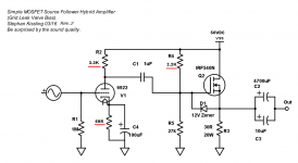
The value of some of the resisters has changed. I have added a cathode resistor (68 Ohm) and I have changed the plate resistor to 3.3K Ohm. This improved the sine wave and increased the gain.
When I load tested the amp, I found the bias needed a bit of tweaking to center the sine wave. So R4 is now 2.2K Ohm.
The output is now just under 4W on the onset of clipping.
These values are for a 50Vdc supply on the rail.
I did run it with a pre amp just for the sake of it, but it is not really needed. That is what your 6922 is for.
Attachments
Last edited:
Great - thanks for the update. Still waiting for 6922. I actually have some copper clad boards now and may try to etch my very first PCB for this project 😀
I have had PCB's made in Singapore for $10 (works very well Apex FX8) but takes a month.
I have had PCB's made in Singapore for $10 (works very well Apex FX8) but takes a month.
In preparation for the tube's arrival, I realize I don't have tube sockets. Is there a budget way to connect tube pins? Is it ok to solder flying leads to pins?
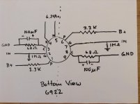
I was looking at your photo and tube pin out diagram and just realized that the tube and your protoboard amp has two sides - stereo in one tube. That's convenient. 🙂
I was looking at your photo and tube pin out diagram and just realized that the tube and your protoboard amp has two sides - stereo in one tube. That's convenient. 🙂
Last edited:
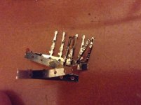

Soldering to the pins is just not going to work reliably (the pins will wick away to much heat to get a good solder), but Glossmaster's idea would get you going.
Valve sockets are cheap though so do yourself a favour and get some.
Shoog
Valve sockets are cheap though so do yourself a favour and get some.
Shoog
Soldering to the pins is just not going to work reliably (the pins will wick away to much heat to get a good solder), but Glossmaster's idea would get you going.
Valve sockets are cheap though so do yourself a favour and get some.
Shoog
Just ordered some sockets, they were about $1ea.
I've two 176mH/0,5Rdc inductors can they be used instead of the 30R resistor?
No, the inductor would not work. Use 3 x 10w 100R in parallel to experiment. They will get very very hot (130C), dissipateing around 35W. So be careful of where you place the resistors. Mine are on the heatsink. I am waiting on some 50W 27 ohm resistors for the proper build.
Alternatively you could try a suitable incandescent light globe with preferably a carbon filament. (In the US 110v/300w I think)
🙂:
- Status
- Not open for further replies.
- Home
- Amplifiers
- Solid State
- Simple Class A Hybrid MOSFET Source Follower