15 to 33 ohms will work as long as they can take the heat. I would personally go a bit more complex with the mosfet bias generator. Reducing noise and removing its loading effect on the tube. I would also enforce some bandwidth limitations.
Attachments
Last edited:
That looks interesting - so the tube output feeds into the 1uF cap? What does setting the voltage at 30v via the two two Zeners do?
I've some 22R/50W are they to low?
I did some measurements with a 20R resistor and found it reduced the output dramatically before clipping. You are better of to have two of your 22R in series.
That is providing that all the values are as per revision 2 schematic.
You can leave the interstage cap out if you like a clean signal path from input to out put.
Interesting certainly.
But Why? Nelson Pass hands out his class A designs freely.
Good doesn't even come close to doing those justice
IMO Dubious that yours Will perform similarily let alone better.
Simple pride ? Or more interested in the Journey than the end product?
But Why? Nelson Pass hands out his class A designs freely.
Good doesn't even come close to doing those justice
IMO Dubious that yours Will perform similarily let alone better.
Simple pride ? Or more interested in the Journey than the end product?
Interesting certainly.
But Why? Nelson Pass hands out his class A designs freely.
Good doesn't even come close to doing those justice
IMO Dubious that yours Will perform similarily let alone better.
Simple pride ? Or more interested in the Journey than the end product?
I did note earlier that it reminds me of the deLite amp. But it is different with a tube follower front end. Who ever said this is better or worse than a Pass design? And just because Mr Pass gives away designs does it mean we can't try to come up with our own? I am glad that Glossmaster suggested this. This is the nature of DIY.
Interesting certainly.
But Why? Nelson Pass hands out his class A designs freely.
Good doesn't even come close to doing those justice
IMO Dubious that yours Will perform similarily let alone better.
Simple pride ? Or more interested in the Journey than the end product?
Interesting! That is why. This is a simple circuit that allows one the play around with tubes and transistors and happens to sound quiet nice.
It is not to outperform any other design.
It is to produce it's own sound.
If there would be one amplifier better than all the others in a given price class,
why do people not just buy "The One"!?
Because tastes do differ. Quality of music reproduction is only objective for does that belief in strict measurements and numbers.
In the real world however, the quality of music reproduction is very subjective.
I am interested in the Journey and the end product. But i am an individual and therefore I have an individual taste.
And that is the beauty of DIY. One can truly be an individual!
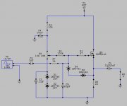
The original circuit needed a coupling cap to be called grid leak bias, and there wasn't one shown. The 6922 is a very good tube when used right. I'd put a volume control after it. It will run more linear with a higher voltage. Put a passive Rf filter at the input. The 22p cap in the circuit on this page will roll you off at 7mHZ. Putting a 2nF cap there instead will roll you off at 80kHZ. Digital sources can have low level Rf energy that is not helpful. The output impedance might be a bit high, which can un-calibrate a passive crossover in a speaker system. I'd measure that. Global negative feedback might be wise if the output Z is over 0.5 ohms.
The 22r shown in post41 is the output device Source resistor.
It sets the bias for the ClassA output stage.
If one assumes the maximum output is 20Vpk, equivalent to 25W into 8ohms, then the bias current should be set to >= 20Vpk/8 = 2.5A
To allow that bias to pass through the combination of mosFET and Source resistor, one would set Rs = 10r and dissipation would be 62.5W. Q1 needs a very big cooler !
A pair of 22r 50W in parallel is equivalent to 11r 100W. That will do the job and allow upto 2.2Apk to the load. Well quite a bit less because a resistor source load allows the stage to generate high 2nd harmonic.
2.2Apk and an 8r0 dummy load is equivalent to 19W from the Buffer.
A 2.5A CCS will allow higher outputs at lower distortions.
Last edited:
post42 shows D1=D2 = 15V Zeners
That places more than 30V on the gate of the mosFET.
When the output is biased to mid supply rail @ ~25V the gate should be around 4 to 5V above the mid rail voltage.
i.e. ~29 to 30V
The Zeners should add to less than that to keep the variable resistor R5 off it's end stop.
I suggest a pair of 12V Zeners, or a 12V + 15V, to allow the VR to operate.
C3 is a bit big, C1 rolls off the bass at a higher frequency than what C1 passes into the amplifier.
This generates avoidable distortion.
Change the ratio of C1:C3 to reduce the audio and sub-audio signals on the speaker capacitor.
I would try C3 @ 330nF to 680nF (F-3dB ~4.7Hz to 2.3Hz)
Last edited:
If I want to use incandescent light bulbs as the bias resistor - how do I go about selecting the bulb? Would two 25w 110v bulbs in parallel basically serve as a 50w resistor for 50v potential?
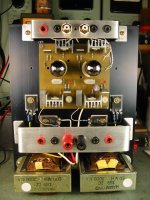
My valve tubes arrived from China. Still waiting for sockets and then sort out this lightbulb or power resistors. I will probably use a fan cooled heatsink so dissipating 60w is not a problem.
My valve tubes arrived from China. Still waiting for sockets and then sort out this lightbulb or power resistors. I will probably use a fan cooled heatsink so dissipating 60w is not a problem.
Last edited:
If I want to use incandescent light bulbs as the bias resistor - how do I go about selecting the bulb? Would two 25w 110v bulbs in parallel basically serve as a 50w resistor for 50v potential.
64.36 -- Light bulbs in series and parallel
In a resistor loaded stage such as this, having the output set to 1/2 B+, the negative half cycle will always clip first. Ideally we want to increase the voltage across the resistor until it clips symmetrically. This is where the output power will be the greatest for a given load resistor.
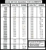
Another alternative for high power resistors are actually hot water heater elements. I have a pair of 4000watt 240volt elements I use. They test at 14.8/15.2 ohms when fed 30 volts.
Another alternative for high power resistors are actually hot water heater elements. I have a pair of 4000watt 240volt elements I use. They test at 14.8/15.2 ohms when fed 30 volts.
Attachments
Plain incandescent automotive lamps would be better suited to low voltage applications.
Why not just bolt one or two of these or similar to a decent size heatsink?
2X 15*OHM 50W Wirewound Aluminum Housed Resistor 50 Watts | eBay
Why not just bolt one or two of these or similar to a decent size heatsink?
2X 15*OHM 50W Wirewound Aluminum Housed Resistor 50 Watts | eBay
An externally hosted image should be here but it was not working when we last tested it.
'Cuz the glow lamp looks way cool. Also, it's radiated off as heat and you don't have to get your heatsink more baked than it already is with the transitor load.
What an interesting approach 🙂An inductor will double the efficiency, but at much higher cost - in Australia, I had two built, each of 100mH 0.47 DCR with 0.5mm gapping and GOSS for $250 EACH. I'm trying for 45W into 8R from 4A quiescent and 36V rails, 144W dissipation from each channel.
Hugh
Hugh, my old class A is just a doorstop nowadays. Would you like to have it, free? The basic hardware would suit you fine for experimentation. The only proviso is you have to come and get it. It weighs just over 50kg. --> http://www.diyaudio.com/forums/solid-state/6338-my-first-ever-class-amp-5.html#post3518394
Edit - this is what my circuit ended up being -> http://www.diyaudio.com/forums/solid-state/6338-my-first-ever-class-amp-4.html#post855313
Last edited:
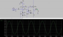
It's a no global feedback stage.In a resistor loaded stage such as this, having the output set to 1/2 B+, the negative half cycle will always clip first. Ideally we want to increase the voltage across the resistor until it clips symmetrically. This is where the output power will be the greatest for a given load resistor.
Another alternative for high power resistors are actually hot water heater elements. I have a pair of 4000watt 240volt elements I use. They test at 14.8/15.2 ohms when fed 30 volts.
It does not clip like a global feedback stage.
It starts to generate 2nd harmonic as the output level increases.
By the time the output voltage is up around 50% of maximum, the distortion is just becoming visble, as a change in shape, on the scope.
Last edited:
Is the distortion mechanism with using a resistor as a current source caused by the variation in current with frequency (not flat)?
distortion due to not maintaining the linear amplification as the signal level changes.
It's typical of all ClassA single ended stages.
Sometimes we design for only using a limited portion of the output level capability to help keep the linearity reasonable.
Or we use NFB to linearise the output with signal level. That allows a higher proportion of the output to be used, but the downside is the sudden onset of clipping when the NFB runs out of headroom.
It simply has to do with the fact that the resistor can not sink as much current as the mosfet can source. It can easily be seen in the following examples, with the output set at 26 volts and 36 volts, the output before the negative half clips increases. ~39 volts is where it begins to clip symmetrically. At this point the output is ~6 watts compared to 26 volts where the output is only ~3 watts.
Attachments

Last edited:
- Status
- Not open for further replies.
- Home
- Amplifiers
- Solid State
- Simple Class A Hybrid MOSFET Source Follower