The throat chamber can only be square or rectangular in the Hornresp inputs so it's a simple volume calculation.
Just to clarify - the throat chamber is modelled as a cylindrical duct, with the Hornresp inputs reflecting this.
Cylinder radius = Sqrt(Atc / Pi)
Cylinder length = Vtc / Atc
If Atc is unknown, simply set Atc = Sd
Assuming that the driver is not oriented back-to-front, the "conical" air volume in front of the driver diaphragm should be included as part of Vtc (the driver cone air volume can be calculated using the Hornresp Driver Front Volume tool).
Can the FTA not still be a figure of interest toward the quality of mouth termination with regard to the rate of expansion at the mouth and the outside loading conditions?
The horn flare itself does this as a whole, the flare exit angle is just a small piece of the puzzle.
You pick the flare that gives the characteristics that you want in the applicable environment (boundary loading), and the flare tangent angle at the exit is whatever it is. And it really doesn't matter what it is unless you are trying to match the exit angle to another physical piece, like matching a CD to a throat, or matching one segment to the next segment.
And since it only applies to perfectly round horns and most bass horns are not perfectly round it doesn't really tell you anything at all about non round horns.
Whether you are worried about directivity, frequency response, impedance, excursion, this is all controlled by the WHOLE flare, the mouth exit angle is just a small part that doesn't even apply unless you build the horn round.
I think some people are thinking the reported mouth FTA has some kind of quality that can be used to improve the performance of horn. Unless I'm missing something really major this is not the case at all. FTA by itself really doesn't matter, shouldn't even really be considered unless it's to match exit angle to the entrance angle of another physical piece, and even then only if both pieces are perfectly round. The flare itself, as a whole, (and all the other parts of the horn) is what's responsible for all the characteristics of the horn. FTA just tells you the mouth exit angle of a round horn and that information has very limited usefulness and practically no use at all in the design of a bass horn as far as I can tell.
Just to clarify - the throat chamber is modelled as a cylindrical duct, with the Hornresp inputs reflecting this.
Yes of course, everything in Hornresp (and most other simulators) is round and the schematic drawing reflects this as well. I'm doing a pretty good job of describing things badly, this the third time in this thread I've done this. Clearly I need to pay a lot more attention to what I'm saying and describe things accurately. (It looks square or rectangular in the schematic but not if viewed in 3d, this is probably why I chose the wrong words even though I know it's a round duct.)
Last edited:
Yes of course, everything in Hornresp (and most other simulators) is round and the schematic drawing reflects this as well. I'm doing a pretty good job of describing things badly, this the third time in this thread I've done this. Clearly I need to pay a lot more attention to what I'm saying and describe things accurately. (It looks square or rectangular in the schematic but not if viewed in 3d, this is probably why I chose the wrong words even though I know it's a round duct.)
Hi just a guy,
I know you know, I was just concerned that the statement had the potential to confuse others less experienced 🙂.
Kind regards,
David
You are right to be concerned, misinformation should be corrected. Thanks for keeping me on my toes.
Wow! The quality of information offered in this thread is most excellent! Its gone well beyond the basics here into some very technical and well thought out posts! This could be reformatted as a clinic on horn design if mods were to remove only my posts.
I gotta say it again fellas... to everyone in particular! Thank you for taking the time to contribute so openly and honestly! You guys really know this stuff inside and out! What a resource!
I gotta say it again fellas... to everyone in particular! Thank you for taking the time to contribute so openly and honestly! You guys really know this stuff inside and out! What a resource!
Axisymmetric
@ just a guy et al
Hi, just a reminder, or heads up, there are a number of references & useful info on it here 🙂
That's just 1 for eg 😉
@ just a guy et al
Hi, just a reminder, or heads up, there are a number of references & useful info on it here 🙂
That's just 1 for eg 😉
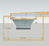
If I make the compression chamber similar to my crude drawing below will that work as well as mounting the driver offset (OD)?

It seems like it should be the same type of result as an OD mounted driver firing into a narrow S1/S2 area, since the driver cone is almost perpendicular to the path in both of these examples.
In this arrangement the driver would still be firing against the baffle wall opposite the cone (at a small gradually expanding angle), but note that between the cone and S1, the baffle material is cut away at angles allowing a compression chamber. A constriction exists at S1 since the compression chamber mouth area is greater than the area of S1. Some S1 attachment flexibility is allowed this way as the driver/chamber assembly can be folded back into the cabinet quite a bit.
Does this work as well as mounting OD? It doesn't violate the integrity of S1 being the beginning of the horn path, right?
Attachments

??? I presume you mean filter chamber, in which case I don't see why not, but the implication without seeing the whole horn is a too high pressure zone for a relatively weak motor [relatively high Qts] driver due to its high aspect ratio and short of being able to accurately sim it may wind up with a too large a compression chamber to balance it out, so if built, then you might want to experiment with smaller than simmed, with the optimum being the net Vb that starts rolling of its low end response and if you can't get to this point, then consider adding a mounting spacer to increase the filter chamber's net Vb.
GM
GM
If I make the compression chamber similar to my crude drawing below will that work as well as mounting the driver offset (OD)?
It seems like it should be the same type of result as an OD mounted driver firing into a narrow S1/S2 area, since the driver cone is almost perpendicular to the path in both of these examples.
In this arrangement the driver would still be firing against the baffle wall opposite the cone (at a small gradually expanding angle), but note that between the cone and S1, the baffle material is cut away at angles allowing a compression chamber. A constriction exists at S1 since the compression chamber mouth area is greater than the area of S1. Some S1 attachment flexibility is allowed this way as the driver/chamber assembly can be folded back into the cabinet quite a bit.
Does this work as well as mounting OD? It doesn't violate the integrity of S1 being the beginning of the horn path, right?
I have no idea at all what's going on from either the picture or the description. All I can gain from this post is that you've set it up a lot more complicated than it needs to be.
If what you are trying to do is make a narrow throat chamber connected to a narrow S1, and have the driver firing into the side of the narrow throat chamber, then the throat chamber is actually part of the path length and should still be simulated as Od for a couple of reasons. First, to get the horn path length right and second, to accurately reflect the fact that the driver is not actually at the end of the line, so it will cause a massive dip caused by the wave bouncing off the closed end of the path and recombining with the main wave on the way out.
Usually we draw horn plans with a top down view of the side profile. Then you can see everything. Your picture doesn't have any details like where the closed end of the horn path is and it looks like S1 is a block of wood at 90 degrees to the beginning of the path.
Please redraw it with a top down view of the side profile so we can actually see what's going on, and it would help if you rough in at least part of the rest of the horn. It doesn't have to be to scale and it can be done is MS Paint or other similar crappy drawing but it will show a lot better what the actual layout is.
Maybe your picture and description is enough for GM to understand what's going on, I haven't got a clue.
Last edited:
DSL's DTS20 is fundamentally the same except a higher CR with a much deeper filter chamber if I understand his drawing/description, but a top section view would definitely help and in my usual haste these days, forgot to ask.
GM
GM
??? I presume you mean filter chamber, in which case I don't see why not, but the implication without seeing the whole horn is a too high pressure zone for a relatively weak motor [relatively high Qts] driver due to its high aspect ratio and short of being able to accurately sim it may wind up with a too large a compression chamber to balance it out, so if built, then you might want to experiment with smaller than simmed, with the optimum being the net Vb that starts rolling of its low end response and if you can't get to this point, then consider adding a mounting spacer to increase the filter chamber's net Vb.
GM
Filter chamber? In Hornresp its called the driver compression chamber I think... something like that. And yes, the volume of the chamber should be as small as practical according to the sim. I don't understand about the aspect ratio and QTS stuff you are talking about though, its over my head.
S1/Sd defines the compression ratio and I'm going with 2.5:1 ratio at this point, as shown on the Hornresp parameters screenshot I posted earlier... subject to change.
Both yourself and Just a guy have demonstrated and explained to me everything that I need to know about the chamber. I understand it all and I'm still looking for a cheating advantage.
Its my nature... I cheat and skirt the technical rules every chance I get! There are ways to ignore a law of physics in certain conditions if you are clever. I used to build methanol racing motors as a partner in an unlimited class racing team. Our team was dominant. And I mean DOMINANT! We took all the money home most weekends, because my partner was a great driver and because I'm really good at racing engine building, and because I'm really good at cheating!
Don't worry I don't cheat humans ever, just technical stuff once I come to understand it.
I have ideas for the chamber and they're no different than what has already been done by others.
The 'next piece', be it a room corner or free space ought to be a continuation of the correct flare, especially if the horn has not reached the needed size by that point lest there be the potential for a reflection. Of course it can be done, just not carelessly.FTA by itself really doesn't matter, shouldn't even really be considered unless it's to match exit angle to the entrance angle of another physical piece, and even then only if both pieces are perfectly round.
I think when David says round, he is saying the calculations are most likely to be realised in the round case. Of course a square cross sectional section of spherical radiation id a feasible wavefront shape and rooms are closer to square, and where the horn cross section is small the shape hardly matters anyway.
After rereading this several times I'm almost 100 percent sure that what you have here is an offset driver layout, but you are attempting to use the chamber as the first segment so it can be looked at as end loaded. This is bad for two reasons as previously stated, the chamber in this case would actually be the first segment in the horn flare and the sim wouldn't include the closed end reflection dip. There's nothing wrong with laying it out like this but simulating it as Nd is not the right way to do it. And you will probably find that the constriction at "S1" (which should actually be S2 in the sim) is going to waste a lot of cab space.
I've redrawn what I think you are trying to show from the top down side profile view. This has the constriction at where you had S1 and shows a bit more of the path, showing that the constriction will require an actual board and might be wasted space as a result depending on how the rest of the horn is laid out.
What I've drawn here SHOULD be simulated as offset with S1 being the closed end for the reasons previously stated. Then the chamber would be defined as the 1st segment, between S1 and S2. It will sim much more accurately if you sim it like that.
It seems to me that you are desperately trying to fold this and keep it Nd but if my pic is accurate this is not Nd, it's OD. And there's nothing wrong with OD, but it should be simulated as OD so the sim accurately reflects the actual path length and the enormous boundary cancellation dip caused by the end wall.
I've redrawn what I think you are trying to show from the top down side profile view. This has the constriction at where you had S1 and shows a bit more of the path, showing that the constriction will require an actual board and might be wasted space as a result depending on how the rest of the horn is laid out.
What I've drawn here SHOULD be simulated as offset with S1 being the closed end for the reasons previously stated. Then the chamber would be defined as the 1st segment, between S1 and S2. It will sim much more accurately if you sim it like that.
An externally hosted image should be here but it was not working when we last tested it.
It seems to me that you are desperately trying to fold this and keep it Nd but if my pic is accurate this is not Nd, it's OD. And there's nothing wrong with OD, but it should be simulated as OD so the sim accurately reflects the actual path length and the enormous boundary cancellation dip caused by the end wall.
I found this image on another forum and I modified it. I labelled S1 at the constriction. This is not exactly as I drew earlier but is similar enough to be the same.
Edit: Aye... we were both posting at the same time.

Edit: Aye... we were both posting at the same time.
Attachments
Last edited:
The 'next piece', be it a room corner or free space ought to be a continuation of the correct flare, especially if the horn has not reached the needed size by that point lest there be the potential for a reflection. Of course it can be done, just not carelessly.
Yes but the flare as a whole and the resulting simulation already account for the radiation resistance of the environment (boundary loaded or not). If FTA was never shown it wouldn't (and shouldn't) affect your sim AT ALL for the purpose stated here. The flare itself AS A WHOLE determines if the mouth is big enough for the horn to function properly in it's environment and FTA alone tells you NOTHING AT ALL about that.
I'm really not sure what you are trying to say, can you explain how you propose to use Hornresp's flare exit angle as part of the design process and why? And not in general terms, give an actual FTA number and explain how that (independent of the rest of the flare) applies to the radiation resistance of the environment.
I think when David says round, he is saying the calculations are most likely to be realised in the round case. Of course a square cross sectional section of spherical radiation id a feasible wavefront shape and rooms are closer to square, and where the horn cross section is small the shape hardly matters anyway.
When David says round he means round, in that the reported FTA ONLY applies to round horns. If you make it rectangular the FTA would be something completely different than what Hornresp reports.
Last edited:
I found this image on another forum and I modified it. I labelled S1 at the constriction. This is not exactly as I drew earlier but is similar enough to be the same.
Edit: Aye... we were both posting at the same time.
Yeah, this is offset. S1 is the closed end and the constriction is S2. The chamber is the segment between S1 and S2.
If you sim this Nd it will sim wrong. It has to be simulated as OD if you want an accurate sim.
Ok, thats the way I'll do it then. Thanks for your patience and hanging in there while I tried to cheat.
Here's the difference between Nd and OD. The closed end causes a huge notch because the wave is bouncing off the closed end. The distance between the driver center and the closed end determine where in frequency the notch will end up. If you keep the driver very close to the closed end the notch will be fairly high in frequency.
This random sim shows the exact same sim run as Nd and OD. The OD sim has a huge notch, the Nd sim does not. The OD sim is the accurate one when laid out as per the pic you showed. In this sim the notch is pretty high in frequency and doesn't affect your passband but it's still best practice to sim accurately.
It is possible to get the path length right for the chamber (if you do it right and sim it as a very long and narrow chamber) and sim it Nd but the sim won't show the huge notch that all OD drivers have so the sim won't be accurate.
Also the pic you posted shows pretty clearly what I said about the constriction leading to a lot of wasted space in the cab.
This random sim shows the exact same sim run as Nd and OD. The OD sim has a huge notch, the Nd sim does not. The OD sim is the accurate one when laid out as per the pic you showed. In this sim the notch is pretty high in frequency and doesn't affect your passband but it's still best practice to sim accurately.
An externally hosted image should be here but it was not working when we last tested it.
It is possible to get the path length right for the chamber (if you do it right and sim it as a very long and narrow chamber) and sim it Nd but the sim won't show the huge notch that all OD drivers have so the sim won't be accurate.
Also the pic you posted shows pretty clearly what I said about the constriction leading to a lot of wasted space in the cab.
- Status
- Not open for further replies.
- Home
- Loudspeakers
- Subwoofers
- FLH design basics for a dummy