FWIW, I designed for a 60 Hz dip since that's his stated upper limit, i.e. where the XO point is, so theoretically not a good plan to shift the driver ala DSL's DTS alignment.
GM
GM
This driver might not have ideal specs for the requested passband but using Leach's math it's easy to see that it can be used extremely effectively for 18 - 100 hz bandwidth. Furthermore, almost any set of driver specs can be used with Leach's math to provide extremely effective response over SOME bandwidth.
Not really, the driver's Fs is way too high for the intended app.
True, I once refuted that a high Qt driver could be properly horn loaded and used a 2.45 Qts driver to prove it [in a sim of course as it would be way too big to build a POC].
GM
Ok, I'm convinced. With a possible smaller cabinet size for similar sensitivity, extension, output etc., how could I be so dumb to be FLH inflicted!
I simmed both of those THs, thanks for them, both of you. Now I gotta learn about tapped horns so I can make one. Gonna take me some time for all that.
Some basic questions for either of you:
Can I expect to get a good response from a TH with no dips to contend with in the passband? Reason I ask is I don't intend to EQ it, its gotta be flat in the room. Outdoors it doesn't matter... its just noise to listen to while working.
I'll need an HPF to limit xmax out of band, no problem there, but will xmax be an issue within the band, or no?
What can I expect to see for sensitivity (roughly) at one watt? I'm hoping to conserve power because my outdoor system is all solar powered with only about 40 amps @ 13.8 volts continuous available during the day. I use car audio amps and/or small class D rigs.
Thats all I can think of right now.
Thanks, and goodnight.
Some basic questions for either of you:
Can I expect to get a good response from a TH with no dips to contend with in the passband?
Absolutely not, tapped horns are all about dips and peaks. You can minimize the ripple a LOT by using an extremely small throat and adding stuffing but then it won't be focused on performance at all. A lot of diy tapped horns have a remarkably smooth passband but that's not what performs best. Front loaded horns have a lot of dips and peaks too. You don't want any massive dips or peaks in or near the passband but it will still sound pretty good even with the ripple. And the narrow peaks will be substantially reduced due to internal box losses. This isn't something that can be accurately simulated but if you sim a bit of stuffing it will have a roughly similar effect.
I'll need an HPF to limit xmax out of band, no problem there, but will xmax be an issue within the band, or no?
Inside the passband you control excursion with the volume knob. (Or eq down the high excursion frequencies if you want, which is roughly equivalent to boosting all other frequencies.)
All the high power sims I showed were at the power level it took to reach xmax at the first excursion hump above tuning. That's your safe power level. And at that power level you will get the frequency response and SPL level shown at that power level (minus power compression).
What can I expect to see for sensitivity (roughly) at one watt?
Sim it at 1 watt and see. Click the Eg box and put 1 watt for power and the driver Re for impedance. Then run the sim and what you see is what you get. If you want you can input the nominal impedance instead of Re but that won't really be 1 watt. Your driver is 4.14 ohms so it won't make a big difference whether you enter 4 or 4.14 ohms as the impedance. Let Hornresp calculate the voltage that equals one watt for you, run the sim and find your sensitivity.
FWIW, I designed for a 60 Hz dip since that's his stated upper limit, i.e. where the XO point is, so theoretically not a good plan to shift the driver ala DSL's DTS alignment.
GM
Theoretically you want the smoothest possible frequency response through the passband and ideally well past the passband.
But in practical terms it hardly makes any difference, the response at the higher frequencies in tapped horns is so erratic there's nothing you can do to get it anywhere near a textbook crossover rolloff unless you use copious amounts of dsp to flatten the response.
Here's your sim with the last segment length you used (top) and the same thing with the last segment increased to 80 cm to fill in the dip somewhat. Both are shown with a 60 hz 4th order BW low pass. There's no practical difference, the crossover region is a mess for both and neither comes anywhere close to a textbook 60 hz BW 4th order target curve. The amplitude of the first big problem out of band spike isn't really affected either way and that's the problem, not the dip. Arguable it's always best to shoot for the flattest response possible when it has no obvious consequences. in this case there is no consequence, you just shift the dip from the left side of the peak to the right side of the peak.
An externally hosted image should be here but it was not working when we last tested it.
Not really, the driver's Fs is way too high for the intended app.
GM
You could use Leach's math to find the exact optimum specs for the bandwidth like Danley did when he designed the Lab12 driver. Then you could use Leach's math to design the exact optimum horn for the driver specs and intended bandwidth like Danley did for the Labhorn. And then you would probably find out that the exact optimum specs aren't always the best option, like Danley did in both the Lab12 driver AND the Labhorn. He significantly changed the driver and the horn after finding the optimum specs, for a few different reasons.
The point is that you might be able to get slightly better performance by finding the exact optimum specs for both the driver and the horn for the intended bandwidth but it's not going to turn out significantly better than THIS driver in the sims in this thread. Maybe a bit but not a lot.
I don't have the Leach math program installed (and I can't remember where I saved the setup file) to find the optimum driver specs but if you want to supply them I can sim it up (or you can) and see just how much difference it makes for any given horn size compared to this driver. Or just pick a driver with more suitable specs to sim.
It would only seem to appear to apply equal aspect ratio horns (like round), and even then only at the mouth (unless it's conical). What would this data be used for?
Hi just a guy,
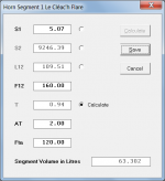
Sometimes a user may wish to specify an axisymmetric horn with a particular throat entry angle to match a given compression driver, and / or specify a particular mouth exit angle. Also, Fta values along the length of the horn can be used set the tapers on individual wooden "slices" glued together in some designs to form the horn contour. It dramatically reduces the amount of manual internal smoothing required, particularly when compared to horns fabricated from a stack of simple stepped "slices".
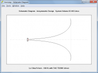
Attachment 1 shows how to specify a 160Hz Le Cléac'h horn with a throat diameter of 1 inch, a throat entry half-angle of 2 degrees, and a mouth flare tangent angle of 120 degrees.
Attachment 2 shows the schematic diagram of the horn.
Kind regards,
David
Attachments
Thanks. Nice to know what AT is for and the practical uses for this information.
Sounds like it could be used for matching a compression driver exit angle to a waveguide throat angle in the very unlikely chance that you could find that info published for either. (Probably easy to find this info for the diysoundgroup SEOS waveguides and Denovo CDs though, but maybe not from other manufacturers although I've never checked.)
And it could be used to match a CD to a diy Synergy horn throat assuming the diy'er has the skills to actually make an accurately angled horn throat out of wood.
So the FTA could be used to calculate the panel angles for something like a 2 step conical horn like a Synergy? That could be useful but I think Bwaslo's Synergy spreadsheet already does this in some detail.
Anyway, as I suspected, most of the practical uses for this info have to do with tweeter horns and waveguides, not bass horns.
Horn performance, like any other "machine" or system, at the end of the day is no more than the sum of its parts. Each "part", or section of a horn should be optimally designed. Further, each part should compliment or "add" value to all those other parts within the system, structure or machine, however you decide to visualize it. A "part" to be a target for optimization can be a physical part of the horn from the largest down to the smallest that can be identified or defined by the designer. This sum of optimal parts adding to compliment the whole include acoustical waves and air within the system as well. Each element of a horn that can be defined should receive our attention in a perfect world.
It seems to me that the FTA feature inside the Segment design wizard/tool may indeed be very useful in a low bass application. In all horns whether low frequency or high, the volume, length and taper angles are what define the expansion characteristics of the acoustic waves within each segment. Therefore, each segment of a horn holds a potential to add value to the whole. I find the FTA feature in Hornresp to be very interesting and potentially very, very useful in the design of any horn, bass horn or not. I intend to take full advantage.
It seems to me that the FTA feature inside the Segment design wizard/tool may indeed be very useful in a low bass application. In all horns whether low frequency or high, the volume, length and taper angles are what define the expansion characteristics of the acoustic waves within each segment. Therefore, each segment of a horn holds a potential to add value to the whole. I find the FTA feature in Hornresp to be very interesting and potentially very, very useful in the design of any horn, bass horn or not. I intend to take full advantage.
Bass horns are almost never axisymmetric. If you look hard you might find a few examples that are but they would be extremely uncommon. A folded bass horn made from flat sheet goods and having two parallel walls like most bass horns cannot be axisymmetric. I don't think it would even be possible to make an axisymmetric tapped horn, the throat would be too small to accomodate the driver unless it was an abnormally large throat. Even if it could be done it would be nearly impossible to fold it into a rectangular box.
So like I said it's not useful information for most bass horns.
It doesn't matter anyway, FTA is not a performance spec and it really doesn't matter what the FTA in a bass horn is.
So like I said it's not useful information for most bass horns.
It doesn't matter anyway, FTA is not a performance spec and it really doesn't matter what the FTA in a bass horn is.
Here's an example of an axisymmetric bass horn. Is this what you want to build?
This could be folded and still be axisymmetric but it would be almost impossible to fold this into a rectangle with two parallel walls like a common folded bass horn. I'm pretty sure it could have a more square profile and still be axisymmetric, but it would still be almost impossible to fold into a rectangle with two parallel walls.
An externally hosted image should be here but it was not working when we last tested it.
This could be folded and still be axisymmetric but it would be almost impossible to fold this into a rectangle with two parallel walls like a common folded bass horn. I'm pretty sure it could have a more square profile and still be axisymmetric, but it would still be almost impossible to fold into a rectangle with two parallel walls.
Last edited:
I like you jag but you and I are not cut from the same cloth.
There is a saying that goes something like this:
Those that can, do.
Those that cannot, teach.
As evidenced above in your FTA argument you have self imposed limits in your thinking. Those limits to open thinking can provide comfort if comfort is your goal. Your excuse and example for FTA not being useful in design apply only to you and your current belief system(s) during these present moments. You may release your mind from self imposed control at your leisure and until the moment that you do, you will be taught, self limiting your potential to do. Your example is lame as well and proves nothing outside of your own mind.
I feel a very strong respect for you and am drawn to your posts on this and other forums that you frequent. I learn a lot from you so I'm always grateful when I find your posts. I appreciate your willingness to share knowledge and your willingness to teach in order to help so many others advance as you have!
I do not appreciate your attempt to teach what appears as nothing more than your personal belief system(s). Please do not attempt to force confined thinking onto others such as myself. It isn't fair play.
Good day,
This is not a tapped horn thread. I am sticking to my original decision. I will continue to work on a front loaded horn design for my crappy driver. I find as many (differing) shortcomings with tapped horn as with FLH and more than one are unacceptable to me. I'm not willing to change direction today. I'll fail or succeed on my own terms. I'm ready to accept whatever that result may be.
Thanks to all who have helped me, I am still learning a lot more than I hoped. Now back to work on this critter...
Thanks to all who have helped me, I am still learning a lot more than I hoped. Now back to work on this critter...
I like you jag but you and I are not cut from the same cloth.
There is a saying that goes something like this:
Those that can, do.
Those that cannot, teach.
As evidenced above in your FTA argument you have self imposed limits in your thinking. Those limits to open thinking can provide comfort if comfort is your goal. Your excuse and example for FTA not being useful in design apply only to you and your current belief system(s) during these present moments. You may release your mind from self imposed control at your leisure and until the moment that you do, you will be taught, self limiting your potential to do. Your example is lame as well and proves nothing outside of your own mind.
I feel a very strong respect for you and am drawn to your posts on this and other forums that you frequent. I learn a lot from you so I'm always grateful when I find your posts. I appreciate your willingness to share knowledge and your willingness to teach in order to help so many others advance as you have!
I do not appreciate your attempt to teach what appears as nothing more than your personal belief system(s). Please do not attempt to force confined thinking onto others such as myself. It isn't fair play.
Good day,
Well, axisymmetric means symmetrical around an axis like the round cross sectional horns that the Hornresp schematic shows (you can't see the schematic in 3d but it shows round axisymmetric horns). And like the example in the picture I linked. Not sure how that's lame, that's just the way it is.
There's no easy way (and maybe no way at all) to fold an axisymmetric horn into a rectangular box with two parallel walls. AT LEAST 99 percent of all basshorns are folded and built into rectangular shape with two parallel walls, in other words not axisymmetric.
If you don't want to build a rectangular folded horn with two parallel walls that's up to you, I'm not trying to force anything on you.
Besides, I listed IIRC 3 ways FTA is useful for tweeter horns and waveguides. But since FTA is the flare tangent angle of an axisymmetric horn and bass horns are almost never built in axisymmetric fashion the reported FTA isn't even applicable for the overwhelmingly vast majority of bass horns. These are facts and have nothing at all to do with my personal belief system or self imposed thinking limits.
Go ahead and build a round axisymmetric bass horn if that's what you want to do. Good luck and have fun with it.
Over the centuries there probably have been far more bass horns built with round axisymmetric designs than all those built into a rectangular shape with two parallel walls.AT LEAST 99 percent of all basshorns are folded and built into rectangular shape with two parallel walls, in other words not axisymmetric.
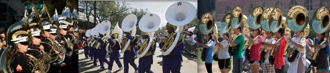
That said, maybe it's time for some new lightweight tuba designs, a rectangular shape with two parallel walls would save a lot of material 😉...
Attachments
Over the centuries there probably have been far more bass horns built with round axisymmetric designs than all those built into a rectangular shape with two parallel walls.
That said, maybe it's time for some new lightweight tuba designs, a rectangular shape with two parallel walls would save a lot of material 😉...
Has anyone tried to mount a BP4 type enclosure (the ported section could act as an compression chamber) to the mouthpiece section of an actual tuba instrument for a true tuba horn subwoofer???
Over the centuries there probably have been far more bass horns built with round axisymmetric designs than all those built into a rectangular shape with two parallel walls.
That said, maybe it's time for some new lightweight tuba designs, a rectangular shape with two parallel walls would save a lot of material 😉...
Yeah, you got me. Most wind instruments are made in axixymmetic fashion.
Once again, clearly I should have chosen my words a lot more carefully. Most subwoofers made from flat sheet goods and using a loudspeaker driver are not made in axisymmetic fashion, and if they have two parallel walls as most do they cannot be axisymmetic. And this is for good reason, axisymmetric designs are very inefficient when it comes to (cubic) space and materials, even though the symmetrical aspect ratio is theoretically superior.
Regardless, I think Hornresp's reported FTA is only applicable to perfectly round cross sectional ducts. I'm not sure if a perfectly square cross section is considered axisymmetric or not but I don't think Hornresp's FTA applies to those either, only perfectly round cross sectional areas.
And if you search hard enough you can find examples of bass horn subwoofers with a round cross section but there aren't many, for several good reasons. But if anyone wants to build an axisymmetric subwoofer (which will end up looking like a tuba or a straightened out tuba if you don't want it folded), go right ahead. It's not going to be space efficient like a normal rectangular box, it's going to require a lot more material, the round profile is going to be a lot harder to make, and it's going to be a lot harder to transport. Don't let these self imposed thinking limits (otherwise known as facts) stop you.
Here's an example of an axisymmetric bass horn. Is this what you want to build?
An externally hosted image should be here but it was not working when we last tested it.
This could be folded and still be axisymmetric but it would be almost impossible to fold this into a rectangle with two parallel walls like a common folded bass horn. I'm pretty sure it could have a more square profile and still be axisymmetric, but it would still be almost impossible to fold into a rectangle with two parallel walls.
Just to clarify - when used to describe a horn loudspeaker, axisymmetric refers to a straight-axis circular cross-section horn (i.e. where the solid profile can be generated using a lathe). The example shown has rotational symmetry, but would not normally be called an axisymmetric horn - and definitely not if folded.
Regardless, I think Hornresp's reported FTA is only applicable to perfectly round cross sectional ducts.
Correct.
I'm not sure if a perfectly square cross section is considered axisymmetric or not
It's not.
but I don't think Hornresp's FTA applies to those either, only perfectly round cross sectional areas.
Correct.
Thanks again jag, I'm looking forward to reading your comments. Do you like BIGG?
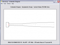
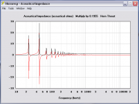
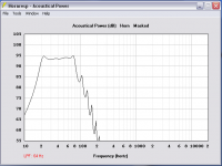
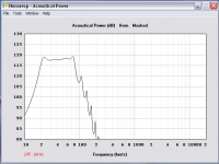
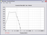
THIS:


Response at 1 watt with 64hz LPF - 2Pi:

Response at 270 watts - 2Pi:

Response at 270 watts - 1Pi:

... is a draft, er a horse... thats it, a draft horse... 😀 BIGG!
I don't think I have the throat adaptor/chamber right. It was done in my sleep several nights ago and I can't figure out how I did it. I don't want to correct it until I understand how it should be done, at the risk of screwing it up worse! I know a calculator was abused, but thats about all I can remember.
THIS:
Response at 1 watt with 64hz LPF - 2Pi:
Response at 270 watts - 2Pi:
Response at 270 watts - 1Pi:
... is a draft, er a horse... thats it, a draft horse... 😀 BIGG!
I don't think I have the throat adaptor/chamber right. It was done in my sleep several nights ago and I can't figure out how I did it. I don't want to correct it until I understand how it should be done, at the risk of screwing it up worse! I know a calculator was abused, but thats about all I can remember.
Attachments

- Status
- Not open for further replies.
- Home
- Loudspeakers
- Subwoofers
- FLH design basics for a dummy