JAG,Probably doesn't matter since he said he's only going to feed it 200 watts or so. His solar panels are only capable of 4 or 500 watts output, so once the solar system and then the typically 60 - 90 percent efficient audio amps get done with converting the sunlight to speaker power (and I'm assuming the sub amp isn't the only thing drawing power) there really isn't a whole lot of power available. Having said that, I like to design for max performance potential too when possible and practical even if it's not going to be used that way immediately or even in the near future.
I would agree with you that designing for maximum potential even if not used (especially when building huge horns) is the way to go.
I don't recall Specd mentioning the details of his amplifier, inverter or batteries, but I have used just four small 12 volt AGM batteries (1 AH at 16.3 amp each) with a cheap Cen-tech inverter (rated 2000 watt continuous, 4000 watt peak) to power a pair of 4 ohm subs and two 8 ohm top speakers for a Christmas parade. Using a Behringer NU4-6000 four channel amplifier, easily putting out over 2000 watt peaks (the subs were hitting clip/limit), surprisingly there was no voltage sag and the inverter only showed a small % of power being used. The inverter was also powering a mixer, a keyboard, a Theramin, and some lights. I have no doubt this small battery/inverter set up could easily deliver well over 6000 watt peak audio power using efficient amplification.
At any rate, we had no problem being louder than the bagpipes in the parade...
Art
To you just a guy... all the posts you offered since I last logged in are exceptional! I won't waste space here on a really long rant (well most likely I will...) but I agree with all your observations and offer just a bit of my personal opinion. Very educational stuff though, all of it and spot on!
In particular I can expand on your observation that many people don't use "best practices" when designing with Hornresp and/or don't build their simulations accurately. Both are absolutely true! When I first downloaded Hornresp a couple months ago I learned how to use it by inputting horn parameters others had posted in various forums, then playing with them observing the effects of my tweaking games. First thing I learned for myself was to leave the wizard sliders alone once a model has been defined. Those are coarse adjustments and within my own mind I couldn't keep close track and understanding of volume/size/length relationships within the horn structures using coarse adjustments. I use the Segment tool and make very small adjustments to one field at a time. Its slow, but my head stays in the game and the quality of my sims are improving each day.
Believe it or not, many of those simulations I have toyed with were very sloppy and unfit for their stated purpose. I easily improved several of them so much in every way that the original posted sim was unrecognisable! Several in particular that are vivid in memory were posted by a fellow who sells his work. Those models he posted were/are actually being sold to the gullible. He tries desperately to sell himself as well in his presentations by making many of the broad and untrue small horn claims you talked about today. Fact is, his work sucks eggs the most! He has no skill at all except for being skilled in selling himself.
Point I'm trying to pound home here is, Hornresp is an extremely accurate and highly precise tool and requires the user to attain both skill in design and to also use "best practices" while using Hornresp. Bad personal habits and/or user haste produce bad results and when something is wrong with the design its always the users fault. The user must fix him/her self for it is they that are in error.
The Hornresp whiners out there either aren't skilled using the tool or they are corporate trolls and/or sock puppets attempting to pry money out of your wallet.
OK, rant energy fully dumped and expended... update time...
To GM and just a guy, my design goals are no longer static, nor are they able to be defined just yet. This is a dynamically changing project where I am using your inputs of knowledge along with the Hornresp precision modelling tool to teach me what my goals must be using my old driver. There will be no excessive force used in the sims. Round pegs will not be nudged into square holes. The driver will be allowed to operate within its range of capabilities in relative comfort wherever possible. That is my approach roughly.
That said, I am still working on my horn sim and probably won't have anything to post on that for a bit, maybe a day or two longer or whatever it takes. I am taking my time on this as I feel that the end is nigh... I want the result to reflect my (and your) best efforts. And one that hopefully will be a bit flexible to small adjustments when it comes time to attempt to fold it into a cabinet
I have changed the sim to OD and I like the new results very much. I have accurately entered the projected throat adapter volumes (1 inch or 2.54 cm Ltc) and cross sectional figures after taking direct and precise measurements from the driver cone. The OD filter notch is well away from the passband and is having no effect on the design. I am very comfortable and happy with it so far. In all indications this horn will exceed my initial expectations.
I'm grateful for all of your help and excited that my personal progress and growth may continue. 🙂🙂🙂
I understand you probably will not be pushing the driver past Xmax, but it is a good practice to make the throat adapter deep enough so no part of the surround or cone will hit at Xlim or Xmech, which may be as much as double Xmax.I have changed the sim to OD and I like the new results very much. I have accurately entered the projected throat adapter volumes (1 inch or 2.54 cm Ltc) and cross sectional figures after taking direct and precise measurements from the driver cone.
I understand you probably will not be pushing the driver past Xmax, but it is a good practice to make the throat adapter deep enough so no part of the surround or cone will hit at Xlim or Xmech, which may be as much as double Xmax.
Yeah, thats good advice. I think Xmech is about 1.5 inches (38mm) or thereabouts to the back plate, can't remember for sure. Cone topout is at 1.75 inches max because I measured the full length of the surround roll. At 1.75 inches though, the surround would be stretched and deformed and quite likely the spider would be overstressed to the max too, with the VC former possibly popped out of the top of the gap, so I think I have a catastrophic event covered if I am calculating correctly.
I calculated for a 1 inch baffle volume + the cone volume and cross sectional result of the adapter yields 24.5 mm for Xmax (from driver mounting gasket), with all of that excursion remaining inside the baffle with 1.5 mm to spare. Additional excursion from 26 mm to cone topout would extend into S1/S2 where there will be over 2 inches of additional excursion space available. That is, if my projected cabinet size holds.
leads me to believe that reactance annulling is not a matter of yes or no, it's a matter of how much.
Exactly 🙂.
The term "reactance annulling" can be a bit misleading in that it implies complete cancellation. The technique is used to reduce the overall reactive component of the system so that more power is delivered to the resistive part of the acoustic load.
Consider a simple example where the input voltage is E and the load impedance is Z where Z = R + j * X.
The real power P into the system is given by:
P = (E ^ 2) * R / ((R ^ 2) + (X ^ 2))
Decreasing the value of X (reactance) increases the value of P (power).
In the limiting case where X = 0, the expression reduces to P = (E ^ 2) / R, which is the maximum available power delivered to resistance R.
In the last couple of paragraphs it actually talks about using a rear chamber vs using both sides of the cone to radiate, in which case they recommend experimenting with lacquer to stiffen up the driver suspension.
I am not sure that is going to help much with a tapped horn, which is what we were talking about 🙂. Try adjusting the value of driver Cms for a tapped horn system in the Loudspeaker Wizard, and see what happens.
@ just a guy
Hi, nice research etc, as usual 🙂 I'm wondering what difference reflexing the back box @ some f around say f3 for eg would make to reactance annulling ? See my 2 examples.
Yeah, I'm not sure how accurate any of that research was. I just stated a few things that seemed to make sense after reading a paper that I don't fully understand. Hopefully David will set all this straight and confirm or deny the validity of the points I made. Maybe we could get Bjorn Kolbrek in here too, a lot of the info covered in that linked paper is also covered in Bjorn's "Horn Theory - An Introduction Part 1. If I have time today I'm going to go through Bjorn's paper again and see if that helps to confirm or deny the validity of my observations. But these papers are all so littered with math that it's a real problem for me to fully understand them.
WRT porting the rear chamber and it's effect on reactance annnulling - I'm not sure. The only way I know of to check for reactance annulling effects is to look for highest sensitivity possible at the low knee, pressures on either side of the cone at the low knee, and the acoustical impedance graph (and I'm not even sure how much that applies since the rear chamber size has no effect on this graph at all).
The paper does say "Experimentally the cavity size (rear chamber size) can be determined by adjusting it until the first major speaker impedance rise occurs at the horn cutoff point. This value is quite high and cannot be mistaken easily."
As I suspected from previous experiments in trying to equalize pressure on the cone with massively undersized horns, this results in rear chamber sizes which are too small to be practical, give a major dip right above the low knee. Equalizing cone pressure and the reactance annulling empirical method quoted above in italics both seem to show that the ideal chamber size for reactance cancellation in massively undersized horn is too small to give a good (or even reasonable) frequency response. It does allow for very low (controlled) excursion though.
I'm not sure how porting the rear chamber would affect things but it's easy enough to find out. Use the empirical method described above in italics and also the pressure equalization graphs to find out if the situation is any better than a sealed rear chamber. Don't forget to check the frequency response while doing it, as optimizing the empirical impedance peak = low knee frequency and/or the empirical pressure equalization method can lead to a very small rear chamber and a bad frequency response with a large dip above the low knee frequency.
By the way, other thing I noticed in the paper which I forgot to mention is that they seem to imply reactance annulling is not even possible if the driver resonant frequency (fs) is equal to or lower than the horn low knee frequency. This paper seems to show a few examples of situations where reactance annulling is either completely impossible or won't achieve a high degree of reactance cancellation even with an ideally sized rear chamber.
In short, it seems that the ideal chamber size for best reactance cancellation in massively undersized horns is impractically small leading to a bad frequency response and even when ideally sized it might not be very effective at cancelling reactance.
But hopefully the experts can say a bit about my conclusions. EDIT - looks like David did comment while I was typing, good stuff.
Last edited:
I am not sure that is going to help much with a tapped horn, which is what we were talking about 🙂. Try adjusting the value of driver Cms for a tapped horn system in the Loudspeaker Wizard, and see what happens.
Yeah, the problem is they are too massively undersized so there's nothing you can do. In a full size or even moderately undersized horn I suspect it would be different, adjusting Cms might have a more beneficial effect.
Like I said, I think that paper (and all papers on this subject) are primarily concerned with full size (or nearly full size) horns and when a massively undersized horn is studied it's hard to get any degree of successful reactance cancellation as the ideal situation for reactance cancellation causes all kinds of problems for other areas like frequency response, and even in the ideal situation the reactance cancellation is not very effective.
First thing I learned for myself was to leave the wizard sliders alone once a model has been defined. Those are coarse adjustments
To make fine adjustments click on the left and right arrow buttons at the ends of the slider bars.
FWIW, while I seriously doubt it makes any difference, it's more convenient for me to transfer designs 'verbatim', which invariably virtually all dims are fractional, so glad you included the option to click on the bar and type in the dimension. 
GM
GM
^ Excellent conversation ^
I was hoping for a bit more conversation on this topic but whatever.
Here's a few pictures to illustrate the points I was making.
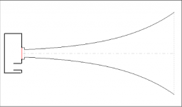
First let's look at a full size horn. This is the one that I mentioned was a stunning example of reactance annulling even though the compression ratio is too high (7:1) and the rear chamber is too small to be practical (although it is the same drivers and ~ same size chamber used in the Labhorn so it isn't THAT impractical).
This was designed by Hornresp's System Design tool, so it's an ideal full size reactance annulled horn for the drivers used in the specified bandwidth (19 - 190 hz) according to Leach's math. This horn has a flare T of 0.8 so it's a bit outside of the ideal 0.5 - 0.7 T range described in the article.
The red line in each graph is right at 19.31 hz indicating that the low knee frequency, the first impedance spike and the total diaphragm pressure minimum all occur at (or extremely close to) the same frequency.
An externally hosted image should be here but it was not working when we last tested it.
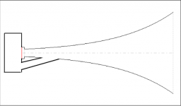
Now let's look at the 568 liter horn that I posted early on in this thread. I changed the flare T to 0.7 to give it the best chance for success according to the article. The rear chamber is 75 liters.
Clearly the low knee frequency, the first impedance spike and the diaphragm pressure minimum do not line up at the same frequency.
An externally hosted image should be here but it was not working when we last tested it.
The article says you should adjust rear chamber size until the low knee frequency is equal to the frequency of the first impedance spike so let's do that. Unfortunately this requires a rear chamber size of 20 liters to get them close, a reduction in chamber size of 50 liters, a full 2/3 reduction from the original chamber size.
The reason this is unfortunate is because the frequency response is now completely ******. There is a sizable 5 or 6 db increase in sensitivity right at the low knee frequency and the excursion is a lot lower and more controlled with the tiny chamber size but the wide 12 db dip right above the low knee is definitely a deal breaker.
To add insult to injury, the pressure spike at the low knee has not been reduced much (if at all) compared to the 75 liter chamber so there doesn't appear to be any advantage at all in trying to size the rear chamber for ideal reactance cancellation as per the article's empirical method of matching the low knee frequency and the first impedance spike frequency.
It does not appear that you can get any practical reactance annulling benefits from this massively undersized horn regardless of the rear chamber size, which is what I've been saying.
An externally hosted image should be here but it was not working when we last tested it.
Last edited:
Your additional explanations have added clarity just a guy. The conversation is great and looks alive to me. None of your efforts are going to waste on me.
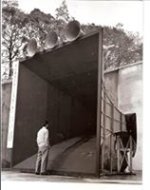
Great horn hm. I wonder are those smaller horns on top of that monster the midrange and uppers of a multi-way getup?
Leach's math must be pretty solid and useful cause I see it mentioned an awful lot. I don't do well around elaborate math but maybe I oughta have a look see. When I've grown up a bit.
For David, I use CTRL+W mostly because I'm afraid to alter more than one horn segment at a time using CTRL+E , else my mind gets scrambled, I forget what I was trying to test/learn for/about, my short train of (empty) thought makes a move on the coffee pot, then once refreshed I must revert all my changes... which means CTRL+E..., THEN CTRL+W. 😀
I find it easier to duplicate the file, re-name with the changes, then compare the multiple files to see the trade offs.For David, I use CTRL+W mostly because I'm afraid to alter more than one horn segment at a time using CTRL+E , else my mind gets scrambled, I forget what I was trying to test/learn for/about, my short train of (empty) thought makes a move on the coffee pot, then once refreshed I must revert all my changes... which means CTRL+E..., THEN CTRL+W. 😀
The most obvious trade off was stated in Hoffman's Iron Law: Low, Loud, Small- pick two.
Designing for 20 Hz response will require a horn about 3 times larger (and heavier, more expensive, and difficult to build) than for 35 Hz to provide equal SPL, but an equal SPL level at 20 Hz will only "sound" about half as loud as 35 Hz...
The percentage of tracks with appreciable content below 30 Hz is rather small, (unless pipe organ or EDM is high on your playlists) so keep in mind the benefit vs. rewards in your train of thought as you compare designs of different size.
http://www.diyaudio.com/forums/full-range/239647-big-time-full-range.html
Art
Last edited:
Leach's math must be pretty solid and useful cause I see it mentioned an awful lot. I don't do well around elaborate math but maybe I oughta have a look see. When I've grown up a bit.
The Hornresp System Design tool is the embodiment of Leach's math. And it's super simple to use. It won't help you learn about why it designs horns the way it does though, you have to read the paper for that. http://users.ece.gatech.edu/mleach/papers/HornPaper/HornPaper.pdf
There are also spreadsheets and programs that do the same thing as Hornresp's System Design tool. The spreadsheet I have is especially useful because you can double click a cell and see how that number was derived. For example, I can click on wc (the parameter I mentioned in the formula from the reactance annulling paper) and see the formula wc =(wl*wh)^0.5, and you can click on those and see how they are derived. Wl = fl*2*PI() Fl, which is a user input, is the desired lower cutoff frequency. Fl should be chosen by making sure the driver is appropriate for the chosen bandwidth, and there's other formulas for that. So you can follow all the formulas back to the user inputs and see how everything fits together.
This is about a million times easier than trying to wade through the Leach paper. And the Hornresp System Design tool is even easier still.
There's also the Eazy Horn spreadsheet that will design stuff for you, it uses aspects of Leach's math among other things, but I find I can get better results by just starting from scratch usually.
Leach's math does have some practical use outside of full size flh theory but if you know what you are doing you can design things other than full size flh just as well without it.
Last edited:
The most obvious trade off was stated in Hoffman's Iron Law: Low, Loud, Small- pick two.
Art
As stated this rule can be broken with money. You can get all 3 if you can afford very high excursion drivers and a lot of power (and maybe a bit of dsp).
If you change "loud" to "efficient" then it's an iron law that can't be broken.
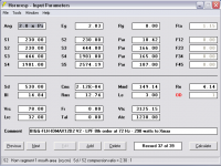
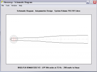
Yep weltersys. I am stubborn but once its beaten into me I come around. Was just getting ready to post this improved box when you posted. I'm slowly warming up to realities. Here 'tis, my latest, greatest BIGG. Looking forward to your comments!
My IDMAX can't handle 22 Hz, else the response becomes unstable. So, I'm rubbing up against 22 from above it as hard as I can, (just -1 db down to 22) from a stable knee at 24 Hz.
Accepting a higher knee at 24 allows a flat response, plus allows a lower compression ratio (2.3:1), plus increased sensitivity, a smaller sealed volume behind the driver, and gets all that done in a smaller cabinet. F3 is about 21 Hz.
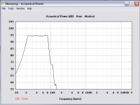
This one is ~753 liters. Its still BIGG, but its got control of the driver I think. I tried other structures on the 22 Hz issue, but none seem to get control of the driver as well as this one. I like it too, because its responsive within a wide range of tweaking. Plus, I can cheat a bit with my Minidsp 2x4 and dial in an 8th order LPF at 72 Hz and have a usable response from 22-80.
Xmax (21.9 mm at 71% BL) is reached at 290 watts using no HPF. This box does 119+ Db in 2Pi and over 125 Db in 1Pi space. There is more sensitivity available if I want to go after it... but then 22 Hz wouldn't be within the passband anymore, and will I really need more?
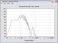
The last screen shot shows the response in 2Pi with 72 Hz/8th order LPF.
I hope to read your opinions of this box, good and bad. I respond most attentively while I'm being poked with a sharp stick, so have at it fellas.


Thanks,
My IDMAX can't handle 22 Hz, else the response becomes unstable. So, I'm rubbing up against 22 from above it as hard as I can, (just -1 db down to 22) from a stable knee at 24 Hz.
Accepting a higher knee at 24 allows a flat response, plus allows a lower compression ratio (2.3:1), plus increased sensitivity, a smaller sealed volume behind the driver, and gets all that done in a smaller cabinet. F3 is about 21 Hz.
This one is ~753 liters. Its still BIGG, but its got control of the driver I think. I tried other structures on the 22 Hz issue, but none seem to get control of the driver as well as this one. I like it too, because its responsive within a wide range of tweaking. Plus, I can cheat a bit with my Minidsp 2x4 and dial in an 8th order LPF at 72 Hz and have a usable response from 22-80.
Xmax (21.9 mm at 71% BL) is reached at 290 watts using no HPF. This box does 119+ Db in 2Pi and over 125 Db in 1Pi space. There is more sensitivity available if I want to go after it... but then 22 Hz wouldn't be within the passband anymore, and will I really need more?
The last screen shot shows the response in 2Pi with 72 Hz/8th order LPF.
I hope to read your opinions of this box, good and bad. I respond most attentively while I'm being poked with a sharp stick, so have at it fellas.
Thanks,
Attachments
Nice flat response.Xmax (21.9 mm at 71% BL) is reached at 290 watts using no HPF. This box does 119+ Db in 2Pi and over 125 Db in 1Pi space. There is more sensitivity available if I want to go after it... but then 22 Hz wouldn't be within the passband anymore, and will I really need more?
119 dB would be louder than I'd listen to in a home theater situation.
Outdoors, listening to music, I'd pick my Keystone design over the latest, greatest BIGG, it's half the size, and goes twice as loud (about +10dB), though does not go as low. But knowing how little of the music I listen to has much content below 35 Hz, that is an easy decision for me to make, but can't say what you really need more of, musical SPL, or rumble 😉.
Art
- Status
- Not open for further replies.
- Home
- Loudspeakers
- Subwoofers
- FLH design basics for a dummy