Hehe, yea, it is getting rather late here, 02:07 and probably time for bed since a few hours..It must be getting late in Sweden, but I've dug up some woofer data:
Imbedanssi 8 ohms
Taajuusvaste 48-4,800 Hz
Fs: 47.5 Hz
SPL: 89 dB 2.83V/1m
Vas: .20,7
Qms: 1.63
Qes: 0.42
Qts: 0.34
Xmax: 4mm
Paino: 1.5kg
And an Le of 0.8mH we knew already. Which is voicecoil inductance. And that is a reflex driver with a smallish xmax.
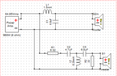
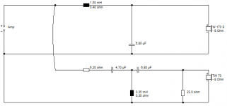
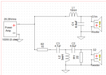
I've been looking at a circuit like below, which seems to do the right things. Now do bear in mind I'm using different, albeit similar, drivers.
Nice to get some data, i hope you know more than me about what to do with it =)
I will simulate that circuit before i got to bed.
Edit:
The black boxes you have in your drawing are inductors right? I notice that it has a resistance?
Attachments
Last edited:
I think im getting close to where i need to be atleast 🙂Yep! 🙂 I mean, once you are close, you can try small changes, like 0.1" at a time. 🙂
Now, play with Steve's stuff for a while, soak up his knowledge. Later we can talk about optimizing your drivers.
It may help you too if you use some of the Circuit blocks in XSim. The L Pad is a good one to start with, it's convenient and will help you set the tweeter level.
You can replace what you see in Steve's notes with the block instead of individual resistors.
Best,
Erik
I will keep playing with Steve's circuits and i think this will be great! Can't wait to hear it 🙂
Just to clarify, show the woofer curve separately?I'd suggest show the bass separately, and change the range on XSim so we can see down to 20 Hz. 🙂 It will help.
I do remember that verry well but i don't think i understood how to 😱Remember early on I suggested the first thing to do was to flatten the bass from the 40Hz level or so? 🙂
🙂
Hehehe. 🙂 XSim FR lets you show the individual as well as combined FR. On the FR window, click "Curves" and select S1, then give it a unique color. You can do this for all 3 curves. Woofer, tweeter and total. UP to you.
S1 (Only) means wihtout the crossover.
Best,
Erik
Hehehe. 🙂 XSim FR lets you show the individual as well as combined FR. On the FR window, click "Curves" and select S1, then give it a unique color. You can do this for all 3 curves. Woofer, tweeter and total. UP to you.
S1 (Only) means wihtout the crossover.
Best,
Erik
Sounds resonable to do that most of the time so you get a feeling of what driver is doing what 🙂🙂
Hehehe. 🙂 XSim FR lets you show the individual as well as combined FR. On the FR window, click "Curves" and select S1, then give it a unique color. You can do this for all 3 curves. Woofer, tweeter and total. UP to you.
S1 (Only) means wihtout the crossover.
Best,
Erik
It's a bit late at night to be doing this! 😀
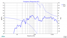
This with that second order 1.5mH/6.8uF bass I suggested. Crossover 3kHz.

Looks like the woofer isn't very flat above the 1kHz surround dip. It's falling away hard. Big hole there around 2kHz. 😕
I couldn't dig up a frequency response for the Peerless bass. Maybe try just a 1.5mH coil, no 6.8uF shunt?
This with that second order 1.5mH/6.8uF bass I suggested. Crossover 3kHz.
Looks like the woofer isn't very flat above the 1kHz surround dip. It's falling away hard. Big hole there around 2kHz. 😕
I couldn't dig up a frequency response for the Peerless bass. Maybe try just a 1.5mH coil, no 6.8uF shunt?
Last edited:
See, I knew Steve was missing the Baffle Step view. 🙂
Try a single pole low pass filter on the woofer. That means just an inductor. Add inductance until the woofer looks as flat as you can make it from around 40 - 80 Hz upwards. Then pad the tweeter down to match the same level. That's a good start.
Best,
Erik
Try a single pole low pass filter on the woofer. That means just an inductor. Add inductance until the woofer looks as flat as you can make it from around 40 - 80 Hz upwards. Then pad the tweeter down to match the same level. That's a good start.
Best,
Erik
Erik, I think the hole is getting worse without the 6.8uF shunt! 😱
I'm fed up with this. Best to sleep on it, in my view! 😀
I'm fed up with this. Best to sleep on it, in my view! 😀
Hi again =)
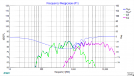
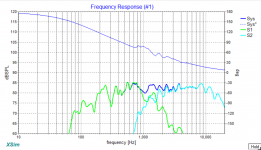
I did a test to add only an inductor to the woofer and increase it until it was as flat as its gonna get before it starts lowering the entire range to much. I ended up with 10mH. Its still not anywhere close to flat in 40-80Hz range?
Then i lowered the tweeter with a resistor and ended up with 24ohm.
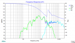
First graph is with 1W amp and S1,S2 driver only. Thought it would be interesting to see how much lower in volume it gets:

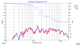
Second Amp 100W+Woofer+system to see the entire graph better:

I did a test to add only an inductor to the woofer and increase it until it was as flat as its gonna get before it starts lowering the entire range to much. I ended up with 10mH. Its still not anywhere close to flat in 40-80Hz range?
Then i lowered the tweeter with a resistor and ended up with 24ohm.
First graph is with 1W amp and S1,S2 driver only. Thought it would be interesting to see how much lower in volume it gets:
Second Amp 100W+Woofer+system to see the entire graph better:
Attachments


Thought i could add this to show woofer/tweeter in that setup:It's a bit late at night to be doing this! 😀
This with that second order 1.5mH/6.8uF bass I suggested. Crossover 3kHz.
Looks like the woofer isn't very flat above the 1kHz surround dip. It's falling away hard. Big hole there around 2kHz. 😕
I couldn't dig up a frequency response for the Peerless bass. Maybe try just a 1.5mH coil, no 6.8uF shunt?
Attachments

Forgot to add the delay of 3.23in.. Now it looks much worse:Hi again =)
I did a test to add only an inductor to the woofer and increase it until it was as flat as its gonna get before it starts lowering the entire range to much. I ended up with 10mH. Its still not anywhere close to flat in 40-80Hz range?
Then i lowered the tweeter with a resistor and ended up with 24ohm.
First graph is with 1W amp and S1,S2 driver only. Thought it would be interesting to see how much lower in volume it gets:
Second Amp 100W+Woofer+system to see the entire graph better:
Attachments

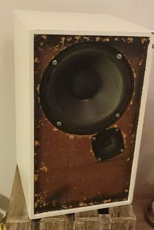
Sultanen, my friend, this is quite a step into the unknown for me.
I've never seen a 6" polycone and cone tweeter design in my life!
You can't run a tweeter with no DC isolation, so a capacitor at least. Tweeters don't like low frequencies, it fries them.
I think your offset between the acoustic centres at 3" is just plain wrong. 1.5" might be closer. Or try flipping the polarity.
To fill the 2kHz hole, we have to make the tweeter work harder. So try a bigger tweeter coil.
Attachments
Thanks alot for the tip about flipping polarity! With the woofer polarity flipped i got this 😀:I think your offset between the acoustic centres at 3" is just plain wrong. 1.5" might be closer. Or try flipping the polarity.
0.77in:
Attachments
Last edited:
Im glad i can give you the opportunity to take this epic journey with me!Sultanen, my friend, this is quite a step into the unknown for me.
I've never seen a 6" polycone and cone tweeter design in my life!
Yea, thought of that but i was just trying to get to some baseline from Erics advice 🙂
You can't run a tweeter with no DC isolation, so a capacitor at least. Tweeters don't like low frequencies, it fries them.
This is the circuit without modification, woofer flipped polarity and offset 0.77in:To fill the 2kHz hole, we have to make the tweeter work harder. So try a bigger tweeter coil.
Attachments

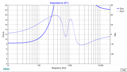
Tried to play around a bit. I put in a bigger tweeter and woofer coil and bumped the tweeter resistor up to level it out and this is the result. But the impedance curve is totally off right?
And i still have no bass =/

And i still have no bass =/
Attachments
And i still have no bass =/
To see what is happening with the bass start by measuring the impedance of the bass driver out of the enclosure and then in the enclosure without any crossover attached. This will tell you the Fr of the speaker in free air and also in the box.
Robert
Thanks for the response!To see what is happening with the bass start by measuring the impedance of the bass driver out of the enclosure and then in the enclosure without any crossover attached. This will tell you the Fr of the speaker in free air and also in the box.
Robert
How do you measure the impedance of the speaker, i figure its not as easy as measuring the resistance across the terminals? =) Can you measure the impedance with a digital multimeter?
EDIT
Is this a doable way of getting a measurment thats within the ballpark? Use the headphone out on the computer.
https://www.youtube.com/watch?v=EMhmVmtQ4BI
-Jonas
Last edited:
I use Room Eq Wizard (REW) to make my speaker measurements. It is freeware and there is a good set of instructions available to explain what to do.
The Help file is here
There is a section on making impedance measurements. The only extra equipment needed is a precision 100R resistor.
I don't think a normal multimeter would work since you need to measure the impedance over a range of frequencies to find the maximum value
Robert
The Help file is here
There is a section on making impedance measurements. The only extra equipment needed is a precision 100R resistor.
I don't think a normal multimeter would work since you need to measure the impedance over a range of frequencies to find the maximum value
Robert
What program are you using to measure your frequency plots? Maybe it will measure impedance too.
Robert
Robert
- Status
- Not open for further replies.
- Home
- Loudspeakers
- Multi-Way
- 2 Way speakers - Suggestions on improvements?