And to minimize HF diffraction artifacts off the hard edges- might be a 2nd or 3rd order effect but easy enough to get at them with a dremel or something. In fact, one could cut out a section of the horn and inset the spacer into that allowing for the profiling to be done in the 3d printing process.
You mean like this?
Hole repair and test insert:

This one is chamfered on backside but not on front to provide maximum waveguide surface.
Attachments
Interesting- Yeah, those could work, but I meant more as an integral part of the spacer design- the spacer would extend all the way into the horn and act as part of the surface (this does that but in several pieces)
Another thing I haven't seen much work done on is utilizing absorptive material in the midrange input- I imagine you could have some pretty dramatic shifts based upon that
Another thing I haven't seen much work done on is utilizing absorptive material in the midrange input- I imagine you could have some pretty dramatic shifts based upon that
You mean like this?
Hole repair and test insert:
This one is chamfered on backside but not on front to provide maximum waveguide surface.
X your building is really excellent. 3D printing actually increases the performance and quality of results greatly.
Although your polar measures apparently not reflect any significant damage caused by the bandpass holes for the woofer, I think the suggestion to make the bandpass with multiple holes is excellent to invalidate the possible negative effect of the woofer holes in the overhall system freq response although at the cost of serious risk of causing "chuffing" by increasing the air velocity therein.
It could also be interesting to see what effect have this design if covering the entire output of the holes (as filler for the wall of the horn) setting a small thin metal or plastic grid with good separation of his hatched (2-3 mm) or perhaps even a thin layer (with the smallest possible thickness) of dampening stuff that could always be placed with enough rigidity to support the thrust of the woofer air through it.
I understand that these additional jobs I have suggested to "minimize" rather than we can the negative impact of the holes in the wall of the horn are probably too difficult to make conveniently and may not even worth try the effort, but in any case if I thought important at least write them down here if somehow they could be of any use.
Obviously, to avoid causing further problems by placing "obstacles" in the ducts of the woofer is critical that the elements are placed so that they are completely "inert" even with the strong dynamics of the air passing through them and must be placed so they can not make any resonance in any way .
Regards
Last edited:
A similar idea of using multiple smaller holes for midrange was used in this Unity thread from AVSForum with measured results
Unity horn with 2 x Eminence Alpha 6 drivers - Page 3 - AVS Forum | Home Theater Discussions And Reviews
X I have found an interesting 8" woofer that is available in Australia that might work, any chance you might be able to run this one through your sim to see how it compares? Is a 4 ohm driver so probably needs to be in parallel. PDF attached with TS parameters.
BC22WJ06-04 8" Mid-Woofer 4?*, Speaker Drivers Replacement | Wagner Online Store
Current US Dollar exchange rate makes Dayton more expensive here at the moment.
Attachments
Fluid,
Thanks for the link! Just reading it now, but nor sure if I am seeing dramatic differences in the various hole topologies:
Here is the test hole matrix, tape was used to block holes to quickly change configurations.

Here is the data:

Those are some rough looking responses there... The COTS WG's in this thread, if you recall the raw data, look much better.
Sure, I can plug that woofer into the sim and see what happens.
Thanks for the link! Just reading it now, but nor sure if I am seeing dramatic differences in the various hole topologies:
Here is the test hole matrix, tape was used to block holes to quickly change configurations.
Here is the data:
Those are some rough looking responses there... The COTS WG's in this thread, if you recall the raw data, look much better.
Sure, I can plug that woofer into the sim and see what happens.
Peerless BC22WJ06 works
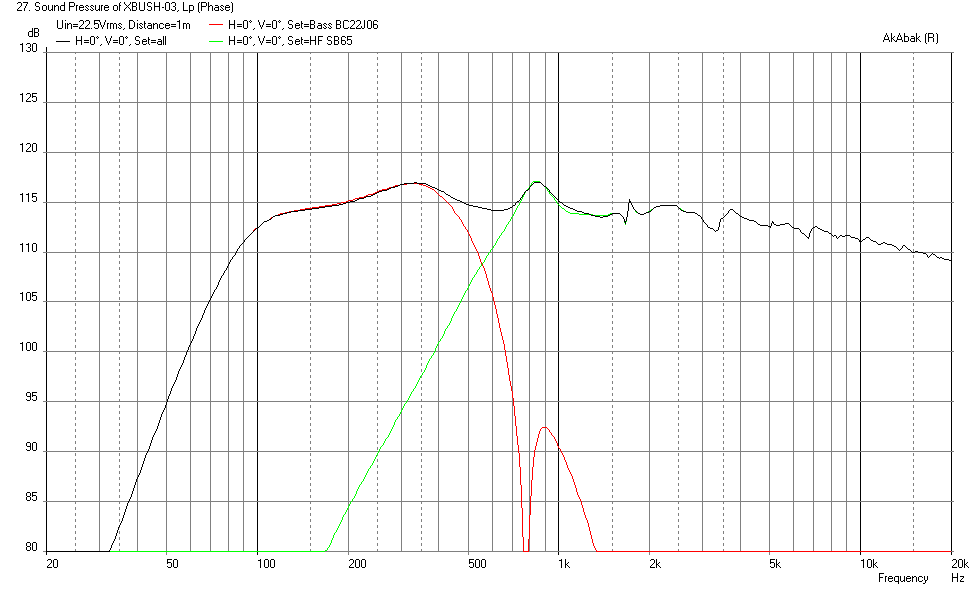
That's a nice driver - very sensitive. You can run them in series for 8ohm and about 91dB or in parallel if you have a 2ohm amp to get 96dB at 2.83v. They have an f3 of 90Hz with an 8 liter rear chamber ea. I have a 6.5in version of this woofer with the polymer basket and it works well. I could not find an xmax spec so assumed it is 7mm. You can getn 114dB output at 22.5v assuming 7mm xmax. Although at that voltage your are putting 280 watts into them and do so for more than a few seconds and magic smoke will come out 🙂
Sensitivity at 2.83v:

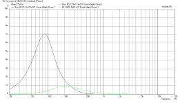
Displacement at 22.5v:

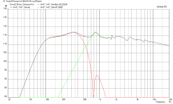
SPL at 22.5v:
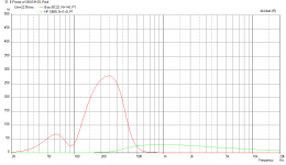
Electrical Power at 22.5v:
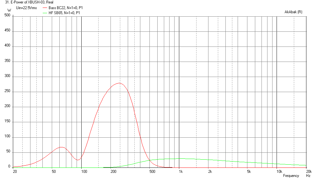
That's a nice driver - very sensitive. You can run them in series for 8ohm and about 91dB or in parallel if you have a 2ohm amp to get 96dB at 2.83v. They have an f3 of 90Hz with an 8 liter rear chamber ea. I have a 6.5in version of this woofer with the polymer basket and it works well. I could not find an xmax spec so assumed it is 7mm. You can getn 114dB output at 22.5v assuming 7mm xmax. Although at that voltage your are putting 280 watts into them and do so for more than a few seconds and magic smoke will come out 🙂
Sensitivity at 2.83v:
Displacement at 22.5v:
SPL at 22.5v:
Electrical Power at 22.5v:
Attachments
xrx971,We can see that the big holes did some damage to the rather pristine polars at the larger angles - with a noticeable dip at 2.5kHz, and the lower frequency extension is not as deep. Although this horn is supposed to be 50deg in this orienation so for 30deg, it is not too bad.
The issues with the polar plots are not readily apparent to my ears.
Surprised to hear that such drastic changes in the polar response are not readily apparent to you, the horn went from moderately "beamy" (narrowing HF response) to twice as "beamy".
From -6dB at 30 degrees off axis at 9k dropped to 2kHz with the large holes (and woofer) and response at 9kHz is virtually gone away, -20 dB.
Hopefully the "hole fillers" will help, but when using a small horn with rapidly changing curve sections it may be advisable to duct the woofer/mid-bass outputs to outside the horn profile.
Art
Attachments

Art,
The scale on the second graph is 5dB/div and I think 9k went down an additional 2.5dB. We are looking at 30deg and that is green line.
The scale on the second graph is 5dB/div and I think 9k went down an additional 2.5dB. We are looking at 30deg and that is green line.
Here is corresponding polars with woofer playing:

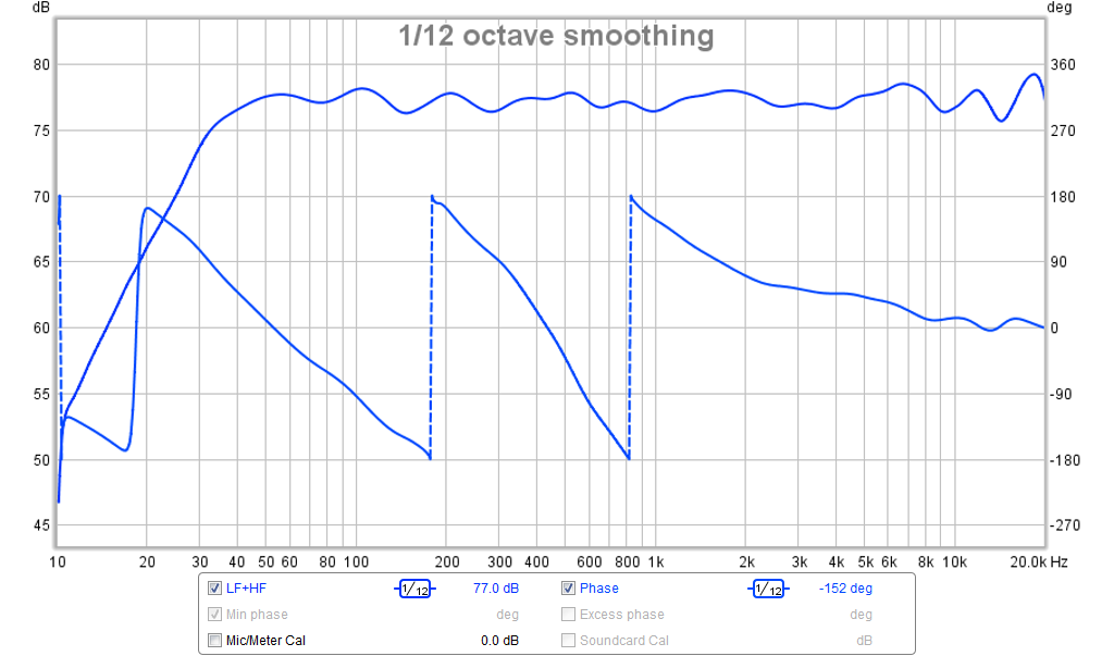
Overall, not too bad with an f3 of 30Hz. Only had a chance to listen to a few songs, but what I hear sounds very nice. The issues with the polar plots are not readily apparent to my ears.
Here is a sound clip from the UMIK-1 recorded to Audacity and converted to mp3. Change extension from .asc to .mp3 to listen. There is some mic hiss - not sure what it's from but don't hear on speaker.
So pattern control is held to roughly 600hz which isn't too shabby for a relatively small horn. I don't think a resistive enclosure would improve things much without a significant reduction in efficiency.
Point source horn
Not trying to sound like a jerk but man thats a little overkill. Some 10" Tannoy point source drivers and a good sub is all you need having a separate sub woofer allows you to find the best position for your room.
Not trying to sound like a jerk but man thats a little overkill. Some 10" Tannoy point source drivers and a good sub is all you need having a separate sub woofer allows you to find the best position for your room.
Is the Tannoy point source a direct radiator sans waveguide? If so - it isn't the same. What we are trying to do here is have controlled directivity to reduce reflections and spray from walls mucking up the sound. I have designed and built many point source FAST direct radiator speakers. They sound great for what they are and are currently my main system. However, they don't do the same things as this horn. You just have to look at the polar response to see the difference.
xrx971,
Surprised to hear that such drastic changes in the polar response are not readily apparent to you, the horn went from moderately "beamy" (narrowing HF response) to twice as "beamy".
From -6dB at 30 degrees off axis at 9k dropped to 2kHz with the large holes (and woofer) and response at 9kHz is virtually gone away, -20 dB.
Hopefully the "hole fillers" will help, but when using a small horn with rapidly changing curve sections it may be advisable to duct the woofer/mid-bass outputs to outside the horn profile.
Art
Completely agree to Art says.
Last polar measurements X do seems is reflecting some degradation on polar response, even if the damage to the wall of the horn of the big bandpass woofer holes appear not very "audible".
I think some tests to reduce the "visibility" to the HF of the big holes of the woofer would be very convenient to try.
Only for test purposses just placing some acustic damper material properly to the output of holes as a "repair" of the horn walls would give the right result and a quick polar measurement could decide its final suitability.
Last edited:
Not trying to sound like a jerk but man thats a little overkill. Some 10" Tannoy point source drivers and a good sub is all you need having a separate sub woofer allows you to find the best position for your room.
I think that you're trying simply to compare ants with cats.
Both are animals but have absolutely nothing at all in common. 😉
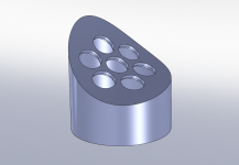
The six hole horn "repair" inserts are printing now. Hopefully they fit and match the horn profile - it was based on the curve on the outside of the horn.
Repair plug insert with six holes now printed. Due to left right symmetry there are two similar ones that had to be modeled and printed. They look pretty good but will have to await until evening before seeing how they fit.
Hey X, have you ever horn loaded any fullrangers with phase plugs? just wondering if the help/hinder the response.
"Pattern control" is generally accepted to be the angle where the nominal dispersion of a horn is -6 dB.So pattern control is held to roughly 600hz which isn't too shabby for a relatively small horn.
In the case of the SB65 loaded 60 x 50 horn xrk971 is working with presently, in the 50 degree orientation, it is "loosing control" below 2000 Hz, and the pattern has expanded to over 120 degrees at 900 Hz, while contracting to about 30 degrees at 10kHz.
The collapsing pattern the horn exhibits is known as "beaming", similar to the piston response expected of a cone loudspeaker of a similar diameter.
Some people seem to like beaming speakers, others prefer constant directivity.
Constant directivity requires a larger horn dimension in the narrower dispersion direction.
A simple formula to roughly figure pattern control is 1,000,000/Horn angle x horn mouth width (in inches).
For a 15" wide horn with a nominal 60 degree pattern, that works out to 1111 Hz pattern control. For a 10" tall horn with a nominal 50 degree pattern, 2000 Hz.
Horns with secondary horn expansions, or large roundovers at the mouth are actually "smaller" than the mouth dimension in terms of lower pattern control.
P.S. , my previous post regarding the change in the horn's response was incorrect, as xrk971 pointed out, the scale on the chart for the horn with woofer holes was 5dB rather than 10dB, the additional beaming was only 2.5 dB at 9kHz.
Art
Last edited:
Art,
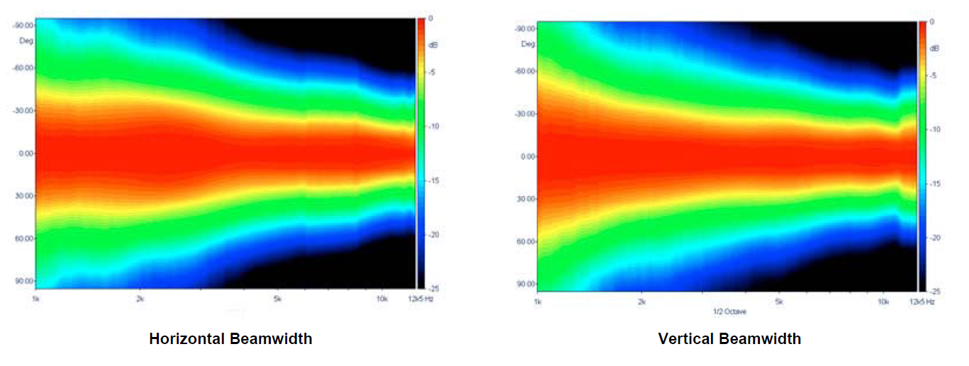
I think what you are describing about the LTH142 is consistent with its beamwidth map. It is after all, a tractrix. The 50 deg (25 deg half angle) specification if you go with the yellow contour where it is -5dB in the Vertical orientaion appears to be good for 3k and up, below which it widens.
Factory beamwidth map for LTH142:
Attachments
- Home
- Loudspeakers
- Multi-Way
- A Bookshelf Multi-Way Point-Source Horn