yes. It's what the temperature de-rated SOAR shows as well.So is it your opinion that 2pair of outputs can produce twice as much power as one pair?
That is where my formula came from after analysing many output stages at many temperatures.
Some time later R,Cordell joined the Forum and posted his guidance in one of his interviews. It turned out that his guidance althogh using apparently quite different parameters arrived at the same conclusion.
Maximum output power is determined by the output device power dissipation capability.
As an aside, if you run the output stage cooler you can get more output power from the same devices because you have used up less of the SOA.
And similarly if you run from lower supply rails you can get a bit more power due to using less of the secondary breakdown area (this does not apply to most mosFETs).
The corollary is that higher temperature and higher supply voltage results in a higher design factor and thus lower power.
Last edited:
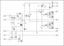
Use 500R (1k) trim pot instead 1N4148 diode to set bias. Amp is overcompensated for working prototype...
Hi Mile,
I will try that. I have seen a few circuits where they use the diode and a trim pot in series. Any good in leaving the diode in circuit?
Do you have some suggestions for the overcompensation issue? Also, is there a way to raise the gain?
Thanks, Terry
Hi Mile,
I will try that. I have seen a few circuits where they use the diode and a trim pot in series. Any good in leaving the diode in circuit?
Do you have some suggestions for the overcompensation issue? Also, is there a way to raise the gain?
Thanks, Terry
Add 2k2 in series with 36k (R2) to rise the gain... bias and gain must be set before proper compensation.
Thanks,
Too busy to work on it today.I'll try to change things tomorrow and we'll go from there.
Blessings, Terry
Too busy to work on it today.I'll try to change things tomorrow and we'll go from there.
Blessings, Terry
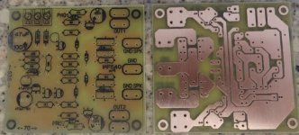
Another PCB layout for mosfet relay protect ,not tested yet 🙂
Regards,Alex
Hello Alex,
Good job, as usual!
Please share to us Sprint-Layout files, are more usefull than JPG or PDF.

hi apex sir, i want to make ax-14 amp.i already knew that sound will be good.i will comment after made.
Can some one with fresher eyes take a look and see i missed something, this is my second channel and when turned on my light bulb will go bright and my psu doesn't even work(led wont even light on). Thanks for the help.
Just build another i got this same problem after i changed the puff capaicator
Can anybody tell what is wrong AX-14 trobleshooting? And yes the transistor 2s5200/A1943 are getting very fast hot
Last edited:
hi apex sir, i want to make ax-14 amp.i already knew that sound will be good.i will comment after made.
Are you starting out with P1 at its highest resistance?
Remove 2k2 resistor (in parallel with 470uF) and protect will detect +/-1V DC offset, use 100uF instead 470uF if you want fast protect... Short circuit protect work only with amp and input signal connected.
Hi Mile,
I pulled the 2k2 and now it will trip the speaker instantly with +1.5vdc from PGND to speaker in/out. However, it takes at least -6vdc to cause it to trip.
Are you starting out with P1 at its highest resistance?
i will etch board today.i think this is for us1070. anyway anything worry about this amp please tell me.thanks.
i will etch board today.i think this is for us1070. anyway anything worry about this amp please tell me.thanks.
Sorry, I quoted the wrong post.
I have built two AX14's. One with TO-3 and one with TO-3p. Both worked first time.
Hi Mile,
I pulled the 2k2 and now it will trip the speaker instantly with +1.5vdc from PGND to speaker in/out. However, it takes at least -6vdc to cause it to trip.
Use this circuit with TO92 triac instead transistors for DC detect.
Attachments
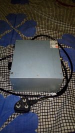
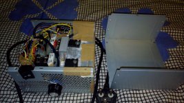
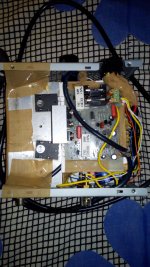
My AX-14 Diy in computer PSU running
I must say very innovative and unique build. BTW what was the problem earlier and how did u solve it?
reg
Prasi
I must say very innovative and unique build. BTW what was the problem earlier and how did u solve it?
reg
Prasi
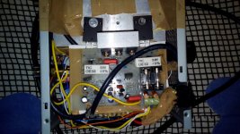
I build 1 with bakelite pcb and 1 with fr4 pcb as shown in the image
The new build fault of bulb lighting up was a mistake i put ttc5200 in the tta1943 slot i changed it started to work.
The old bakelite i build earlier was i put a lower value that is 20pf puff instead of 33pf capacitor which started heating the output transistor c5200/a1943 very fast after some time it gave speaker output of 14vdc look llke some small transistor got damaged. I fixed it by building again.
Last edited:
The old bakelite i build earlier was i put a lower value that is 20pf puff instead of 33pf capacitor which started heating the output transistor c5200/a1943 very fast after some time it gave speaker output of 14vdc look llke some small transistor got damaged. I fixed it by building again.
BD139 vbe multiplier should be mounted on same heatsink along with 2SC5200/2SA1943. Add zobel network at output as suggested by miles.
My concern is amp module directly mounted over EI transformer.
Regards,
Sonal Kunal
Last edited:
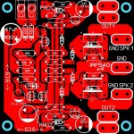
PCB from latest SSR protect schematic.
Please check
Sprint layout file attached
Hi C08bm,
I think Mr. Miles suggested to reduce 470uF to 100uF for faster response. also only one 1n4007.
reg
prasi
PCB from latest SSR protect schematic.
Please check
Sprint layout file attached
I etched a pair.
I'll try one when the MAC97a's arrive.
Attachments
- Home
- Amplifiers
- Solid State
- 100W Ultimate Fidelity Amplifier