you scare easily, I see... 😀And there goes my coffee
🙂
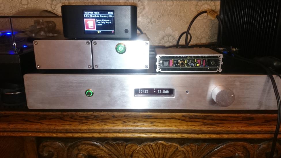
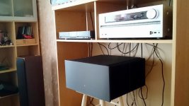
Here's a family photo together with the Honey Badger to show the scale.
Cute Monster ,man. 🙂
Hope you don't have local neighbors - that's a KW total AB amp there !
PS - 25C ? at 60ma bias ? I sort of predicted that. My Slew is in a case
about in between your two. I get about 32-35C . 40C if I really crank it.
OS
Last edited:
Cute Monster ,man. 🙂
Hope you don't have local neighbors - that's a KW total AB amp there !
PS - 25C ? at 60ma bias ? I sort of predicted that. My Slew is in a case
about in between your two. I get about 32-35C . 40C if I really crank it.
OS
Thanks. 🙂
The closest neighbor lives ~30 m from my house. No complains yet. ;-) I run it at around 70ma bias, it idles around 20c above ambient. The 25C picture is showing room temp with the amplifier switched off.
Last edited:
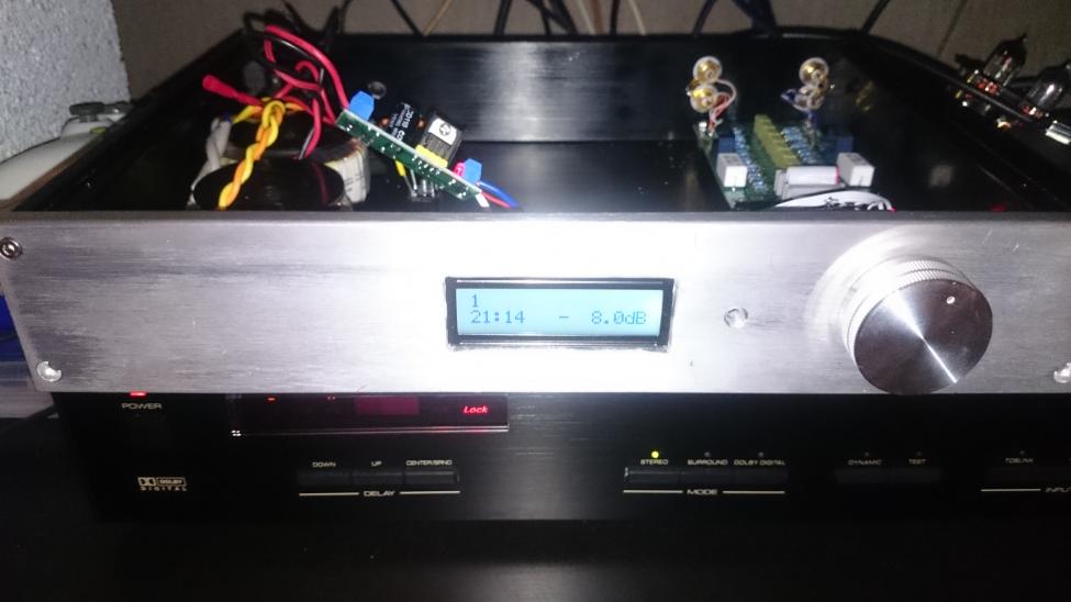
Another Lcduino with attenuator almost finished. This is going to be used with rotel rda975 dac and the Honey Badger. I also built a Y1/Y2 for the other stereo.
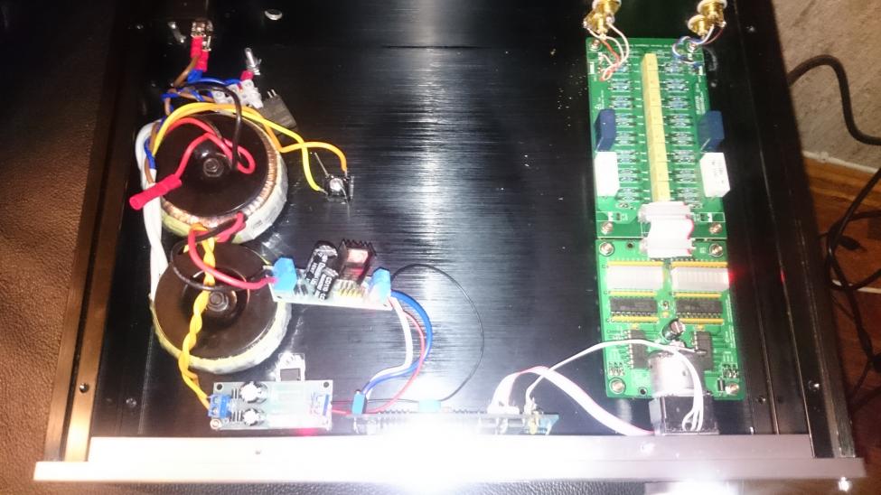
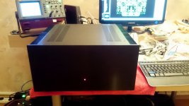
My power amp - CF-FET-V2.0
OK, it's already described in CF-FET thread, here are just some pictures.
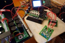
Starting from the front-end PCB and early prototype testing, and ending with a finished "product".
I'm using it as a main power amp in my audio system now 😎
OK, it's already described in CF-FET thread, here are just some pictures.
Starting from the front-end PCB and early prototype testing, and ending with a finished "product".
I'm using it as a main power amp in my audio system now 😎
Attachments
-
 27-SMD-zDSC03869.JPG226.9 KB · Views: 933
 -
 31-DSC03853.JPG370.5 KB · Views: 366
 -
 21-DSC_0092.JPG354.4 KB · Views: 394
 -
 21-DSC_0091.JPG329.7 KB · Views: 441
 -
 21-DSC_0089.JPG493.1 KB · Views: 461
 -
 21-DSC_0078.JPG912.9 KB · Views: 510
 -
 20-DSC03909.JPG353.5 KB · Views: 477
 -
 20-DSC03900.JPG331.1 KB · Views: 920
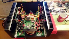
Looks like the front heatsinks are just to for looks. I'm too cheap to do that. 😀 I would have to find something to mount on them. Beautiful amp!
for looks.
Even more ironic when you follow the route/wire from the output coil to the output terminal, Terry.
Coffee? 🙂
Sure, but hope not soluble. Would not look good beside that beautiful amp. 😎
I agree. A little too close for my comfort, but to each their own. My liquids are always kept at least an arms length away. 🙂 No jewelry either when around electronics. Learned that from an old Navy tech about 45 yrs ago.Sure, but hope not soluble. Would not look good beside that beautiful amp. 😎
Great build.OK, it's already described in CF-FET thread, here are just some pictures.
Starting from the front-end PCB and early prototype testing, and ending with a finished "product".
I'm using it as a main power amp in my audio system now 😎
Rod Elliot P101 build
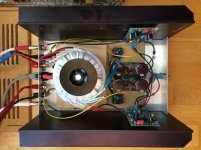
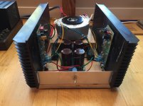
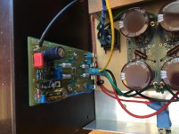
Inspired by Burning Amp, I just finished my new power amp. This is Rod Elliot's design, with his soft-start board and a diyaudio power supply board.
Shockingly clear and analytic so far with my (ridiculously efficient) Pi Seven speakers.
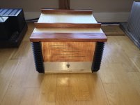
The case is not what I would like aesthetically, but for now it does the job. The metalwork is part of an earthing network that terminates in a star by the IEC socket and at the output end of the power supply.
tim
Inspired by Burning Amp, I just finished my new power amp. This is Rod Elliot's design, with his soft-start board and a diyaudio power supply board.
Shockingly clear and analytic so far with my (ridiculously efficient) Pi Seven speakers.
The case is not what I would like aesthetically, but for now it does the job. The metalwork is part of an earthing network that terminates in a star by the IEC socket and at the output end of the power supply.
tim
Attachments

Neat.Inspired by Burning Amp, I just finished my new power amp. This is Rod Elliot's design, with his soft-start board and a diyaudio power supply board.
Shockingly clear and analytic so far with my (ridiculously efficient) Pi Seven speakers.
The case is not what I would like aesthetically, but for now it does the job. The metalwork is part of an earthing network that terminates in a star by the IEC socket and at the output end of the power supply.
tim
Thank you. The heatsinks are ridiculously large - they are barely above room temperature. I might wind up the bias a bit to see if it makes a difference.
Maybe next time I want to build an amp I'll saw the heatsinks in half...
tim
Maybe next time I want to build an amp I'll saw the heatsinks in half...
tim
Here are my three Maplin amps from the 1980's.
Left hand side is 225WRMS bipolar amp using 2n3055 and mj2955.
Top right is bipolar 50WRMS amp.
Bottom right hand side is 75WRMS mosfet amp.
I bought the first two off ebay faulty and repaired them.
Left hand side is 225WRMS bipolar amp using 2n3055 and mj2955.
Top right is bipolar 50WRMS amp.
Bottom right hand side is 75WRMS mosfet amp.
I bought the first two off ebay faulty and repaired them.
An externally hosted image should be here but it was not working when we last tested it.
Looks like the front heatsinks are just to for looks. I'm too cheap to do that. 😀 I would have to find something to mount on them. Beautiful amp!
Well, the heat still distributes to the front sections, however they are definitely less warm than the back ones. This is a result of not enough thinking when arranging the PSU 😛
Even more ironic when you follow the route/wire from the output coil to the output terminal, Terry.
Very valid observation 🙂 Already thinking about moving the relays right to the output terminals (and probably switching to the SS ones) 😉
- Home
- Amplifiers
- Solid State
- Post your Solid State pics here