Are you running a Mu type of circuit with these devices?
No, it is a push pull totem pole style output. Very similar to the power outputs back in late 60's - early 70's before good complementary devices were available. I like to look back at old circuitry and apply new components to update them. Kind of looks like we have come full circle now that p-channel devices are not as common as they once were. I am interested in using these in a mu circuit though. I think my next experiment will be dropping them into my Amp Camp amps and see how well they work there. Also I'm thinking about trying them in a cascode circuit to exploit their triode region similar to Papa's power Jfet Zen amp.
Hello to my SIC friends here
My new Cree SiC mosfet amp is back in its case ( hopefully permanently), and it is not showing any signs of instability. I was hesitant to try it in my main system until it settled down, so it has been running on test speakers for a few weeks while I developed more trust in its reliability. So last night I could 't stand to wait any longer. I hauled it into the living room and patched it in. I have to say that I expected a little difference compared to my identical amp with Vishay IRFP240 outputs, but not really anything amazing. I'm happy to say I was wrong. The whole character of the amp is different with the C2M1000170D outputs. The amplifier sounds more like a tube amplifier. The sound is slightly less bright than the old outputs were, but it seems more organic and real now. I was worried that with less transconductance than the 240's the Crees might have less ability to drive the low end properly, but it seems plenty capable in that respect. The highs are very nice, not harsh at all. Silky is the word that comes to mind, with everything clearly reproduced but in perfect balance with the rest of the audio spectrum. I especially like the midrange reproduction now after listening to an audiophile choir recording, and various male and female test recordings. The soundstage has seen improvement too with a seemingly greater feeling of depth and sense of the room when listening to live recordings. I notice the sound of room reverberation that I don't remember hearing as well before. So in a nutshell, I am sold on these devices, at least in the PLH style circuit I'm playing with. I wonder if Papa has cleared his plate enough yet to try them for himself ?
My new Cree SiC mosfet amp is back in its case ( hopefully permanently), and it is not showing any signs of instability. I was hesitant to try it in my main system until it settled down, so it has been running on test speakers for a few weeks while I developed more trust in its reliability. So last night I could 't stand to wait any longer. I hauled it into the living room and patched it in. I have to say that I expected a little difference compared to my identical amp with Vishay IRFP240 outputs, but not really anything amazing. I'm happy to say I was wrong. The whole character of the amp is different with the C2M1000170D outputs. The amplifier sounds more like a tube amplifier. The sound is slightly less bright than the old outputs were, but it seems more organic and real now. I was worried that with less transconductance than the 240's the Crees might have less ability to drive the low end properly, but it seems plenty capable in that respect. The highs are very nice, not harsh at all. Silky is the word that comes to mind, with everything clearly reproduced but in perfect balance with the rest of the audio spectrum. I especially like the midrange reproduction now after listening to an audiophile choir recording, and various male and female test recordings. The soundstage has seen improvement too with a seemingly greater feeling of depth and sense of the room when listening to live recordings. I notice the sound of room reverberation that I don't remember hearing as well before. So in a nutshell, I am sold on these devices, at least in the PLH style circuit I'm playing with. I wonder if Papa has cleared his plate enough yet to try them for himself ?
Care to share the circuit you are using with the Crees?
And, by the way, the Cree C3M MOSFET is now in stock in TO247 at Mouser. 🙂
And, by the way, the Cree C3M MOSFET is now in stock in TO247 at Mouser. 🙂
Last edited:
Hello to my SIC friends here
My new Cree SiC mosfet amp is back in its case ( hopefully permanently), and it is not showing any signs of instability. I was hesitant to try it in my main system until it settled down, so it has been running on test speakers for a few weeks while I developed more trust in its reliability. So last night I could 't stand to wait any longer. I hauled it into the living room and patched it in. I have to say that I expected a little difference compared to my identical amp with Vishay IRFP240 outputs, but not really anything amazing. I'm happy to say I was wrong. The whole character of the amp is different with the C2M1000170D outputs. The amplifier sounds more like a tube amplifier. The sound is slightly less bright than the old outputs were, but it seems more organic and real now. I was worried that with less transconductance than the 240's the Crees might have less ability to drive the low end properly, but it seems plenty capable in that respect. The highs are very nice, not harsh at all. Silky is the word that comes to mind, with everything clearly reproduced but in perfect balance with the rest of the audio spectrum. I especially like the midrange reproduction now after listening to an audiophile choir recording, and various male and female test recordings. The soundstage has seen improvement too with a seemingly greater feeling of depth and sense of the room when listening to live recordings. I notice the sound of room reverberation that I don't remember hearing as well before. So in a nutshell, I am sold on these devices, at least in the PLH style circuit I'm playing with. I wonder if Papa has cleared his plate enough yet to try them for himself ?
Hi Mike
Very interesting diy work congratulations and thanks for sharing audio impressions with Your new SIC transistored amplifier.
Do you go on BAF 17 octobre ?
Bring Your class A for the show 😀
Hi Mike
Very interesting diy work congratulations and thanks for sharing audio impressions with Your new SIC transistored amplifier.
Do you go on BAF 17 octobre ?
Bring Your class A for the show 😀
Hi Soundhappy
I would love to be able to attend this year but unfortunately won't be able to make it this year. It is a dream of mine to be there someday to see everybody.
I wish I could share the circuit as built but is is not my design and I don't have permission to do that. But I can tell you that it is very similar to Papa's PLH amplifier in many respects. The output stage is almost identical.
No, it is a push pull totem pole style output. Very similar to the power outputs back in late 60's -
If you have PLH output stage, I wouldn't call that a true push pull output stage as you get current limiting around 1.5 x the bias current.
Hi Soundhappy
I would love to be able to attend this year but unfortunately won't be able to make it this year. It is a dream of mine to be there someday to see everybody.
I wish I could share the circuit as built but is is not my design and I don't have permission to do that.
Nice review. Very encouraging results.
Can you list all devices you have used in this topology.
Thanks.
If you have PLH output stage, I wouldn't call that a true push pull output stage as you get current limiting around 1.5 x the bias current.
Hi Pico
I apologize for my incorrect terminology. In my way of understanding , a totem pole output is two similar polarity stages stacked on top of one another. That describes both the PLH output and the output I am working with. I believe push pull accurately describes both because being made of the same polarity device, the top half must be driven opposite in phase compared to the bottom. This can be done in a number of ways , but whichever way you do it, when the top is being "pushed", the bottom must be being "pulled" to move the output node. Papa's F6 works in a similar way being driven oppositely through use of opposite phase separate transformer secondaries. I am not familiar with the current limitation characteristics you mention, but I would appreciate it if you could explain how that works. I am always eager to learn.
In the days when this topology was common, the bias was typically class B or AB. I have upped the standing current to Class A levels (1.2 Amps) to get performance advantages we are all familiar with. To answer your question about what devices I have used I this topology, I have used bipolar junction transistors ( the original implementation), and IRFP150, IRFP240, C2M0280120, and the current C2M1000170D. I made a stupid mistake while the 0280120's were in the circuit, and blew one out. So I was not able to really listen to that configuration properly. The C2M1000170D definitely sounds better to my ears and to the few others I have had listen.
Last edited:
I am not familiar with the current limitation characteristics you mention, but I would appreciate it if you could explain how that works. I am always eager to learn.
.
I will need to spend some time looking at the circuit to explain its proper function.
The top device limits current through circuit to no more than 1.5 x bias. Below that point it operates like a Class A push pull output stage but it does not continue into Class AB like F6.
I've never completely understood why it current limits except that it acts like a constant current device like Aleph.
I've been away for a few days, but I'm happy to note that progress continues
without me.
😎
Welcome back Papa! It's not the same without you....
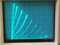
I have been reading the excellent thread by wrenchone in which he talks about Schade feedback. Out of curiosity I built the little IRFP240 example Schade circuit that consists of a 10K feedback resistor drain to gate with a 1K input resistor in series with the gate. I got almost exactly the same curves on my curve tracer that were pictured in the thread. I got to thinking that it is too bad that the input impedance is low ( equal to the input resistor I think), so I thought I would try a similar circuit with one of my C2M1000170D low capacitance SiCMosfets. Since the capacitance is about a factor of ten lower, I figured I could get away with increasing the resistor values by ten also. So I built up the new version and hooked it up to the tracer. I think the curves are very interesting. Not as linear as the 240 curves and quite different in shape. The settings for the photo were as follows:
5 V per division horizontal
100 mA per division vertical
1 V per step gate drive
50 ohm load limiter
5 V per division horizontal
100 mA per division vertical
1 V per step gate drive
50 ohm load limiter
Attachments
Last edited:
not bad
not bad at all
though , neither 1K nor 5K are too low for drive
Thanks ZM. Now what to do with it? Can't hear how it sounds on the curve tracer!
This was meant to be my secret. HahahahaThanks ZM. Now what to do with it? Can't hear how it sounds on the curve tracer!
Just go build it.
Mu Follwer, or Single Ended Choke loaded design. Build Mu Follower first then choke loaded design
I have been reading the excellent thread by wrenchone in which he talks about Schade feedback. Out of curiosity I built the little IRFP240 example Schade circuit that consists of a 10K feedback resistor drain to gate with a 1K input resistor in series with the gate. I got almost exactly the same curves on my curve tracer that were pictured in the thread. I got to thinking that it is too bad that the input impedance is low ( equal to the input resistor I think), so I thought I would try a similar circuit with one of my C2M1000170D low capacitance SiCMosfets. Since the capacitance is about a factor of ten lower, I figured I could get away with increasing the resistor values by ten also. So I built up the new version and hooked it up to the tracer. I think the curves are very interesting. Not as linear as the 240 curves and quite different in shape. The settings for the photo were as follows:
5 V per division horizontal
100 mA per division vertical
1 V per step gate drive
50 ohm load limiter
Initially i felt the curves are all for women but now even for the SIC Jfets...😛.
- Home
- Amplifiers
- Pass Labs
- new SiC JFETs?