What is more interesting is the primary impedance of the Dynaco A470, even though it is spec'd at 4.3k, most measurements on old transformers showed it being closer to 5k or 6k.
Last edited:
diytube.com • View topic - Sanity check of A470 Output Xfmrs
"From my mid 70s Japanese Dynaco A470 (out of circuit, on my bench):
Measured with Wavetek Meterman 37XR:
Center Tap to front plate lead = 87 ohms
Center Tap to rear plate lead = 104 ohms
Center Tap to front screen lead = 29 ohms
Center Tap to rear screen lead = 34 ohms
I measure 10H from center tap to either plate connection."
Good information! This tracks closely with the specifications of the Transcendar version of the A-470 transformer. Thanks for the link.
Hmm, 100H (Transcendar) vs. 20H (measured) doesn't look so close...This tracks closely with the specifications of the Transcendar version of the A-470 transformer.
Hmm, 100H (Transcendar) vs. 20H (measured) doesn't look so close...
Whoops, you're right. I saw 10H (center tap to plate) and read 100H. I'm not sure what to believe at this point...
100H might be a mis-print or just a "marketing spec", since it is 2 lbs lighter than the original, it is unlikely that it has a much higher inductance.
100H might be a mis-print or just a "marketing spec", since it is 2 lbs lighter than the original, it is unlikely that it has a much higher inductance.
Probably a misprint (which I should have realized), since the 60 watt A-431 is spec'ed at 40H for the primary inductance.
Another question about modeling a center-tapped choke...
Let's say I want to model a Tango TC60-15W (plate choke with a center-tap). With the center-tap left unused, and the choke used 'single-ended', the primary L is spec'd at 60H, 730 ohm DCR.
If I use the center-tap to B+ and each end of the winding goes to the plates of a push-pull pair of triodes, should I enter 15H as the inductance and 182.5R for each half of the choke (from center-tap to each end)?
I'm using what I learned about calculating inductance of a push-pull choke to apply here.
--
Last edited:
Each winding is 30H and 365R if they are used separately which isn't really the case for a PP output stage, I think...
6P43P?
Is there, or has there ever been, a SPICE model for the Russian 6P43P-E pentode?
I've collected as many data sheets and curves as I could find. I've attached some to this post, in the (perhaps misguided) hope that one of you SPICE wizards can possibly make a working model out of the info.
In triode, this looks like a beefy and quite linear driver, or possibly the power tube for a small amp (headphone amp?).
--
Attachments
I think I may have it, unfortunately I am on the road, so someone else may have to make you one... Or you can find a close US or EU equivalent and use it.
Unfortunately, and as far as I know, there is no US or EU equivalent to 6P43P. It would be great if I was wrong, though.
6P43P-E triode conneted LTspice model
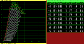
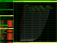
@rongon, I did this in Curve Captor. I guessed at the capacitances. Follows closely the triode connected curves you posted.
Library file output from Curve Captor attached below.
@rongon, I did this in Curve Captor. I guessed at the capacitances. Follows closely the triode connected curves you posted.
Code:
* 6P43P-E_t LTSpice model
* Modified Koren model (8 parameters): mean fit error 0.422938mA
* Traced by Wayne Clay on 6/4/2015 using Engauge Digitizer and
* Curve Captor v0.9.1 from curves posted at: (page #91, post #909)
* http://www.diyaudio.com/forums/tubes-valves/243950-vacuum-tube-spice-models-91.html#post4347016
.subckt 6P43P-E_t  P G K
    Bp  P K  I=
+ (0.1910557097m)*uramp(V(P,K)*ln(1.0+(-0.1946472027)+exp((2.445230247)+
+ (2.445230247)*((9.131534241)+(-20.66037009m)*V(G,K))*V(G,K)/sqrt((23.34295859)**2+
+ (V(P,K)-(6.69768908))**2)))/(2.445230247))**(1.394210234)
* Capacitances are estimated.
    Cgk G K 7.0p
    Cpk P K 5.5p
    Cgp G P 5.0p
    Rpk P K 1G ; to avoid floating nodes
    d3  G K dx1
.model dx1 d(is=1n rs=2k cjo=1pf N=1.5 tt=1n)
.ends 6P43P-E_tAttachments
It looks like inter-electrode capacitances are shown in this datasheet:
http://tec.org.ru/_bd/17/1764_643-.pdf
...and here too: http://www.xsistema.lt/datasheets/download?f=6P43PE.pdf
It looks like one line says 1.3pF, the next 9pF, the next <0.7pF, and the next <0.4pF.
They're in Russian, so I'm not sure which is Cg-k, Ca-k, etc.
--
http://tec.org.ru/_bd/17/1764_643-.pdf
...and here too: http://www.xsistema.lt/datasheets/download?f=6P43PE.pdf
It looks like one line says 1.3pF, the next 9pF, the next <0.7pF, and the next <0.4pF.
They're in Russian, so I'm not sure which is Cg-k, Ca-k, etc.
--
Unfortunately, and as far as I know, there is no US or EU equivalent to 6P43P...
Isn't this very similar to EL86 ?
Isn't this very similar to EL86 ?
According to Klausmobile Tube Tester Files, the 6P33P is an "EL86 clone." He says about 6P43P-EV: "I give up, cannot find data on this tube, heard that it is 6P18P version, although it does look differently."
I'm looking at the data sheet for EL86, which has triode curves on page 'G.' It looks like it's sort of close to 6P43P in triode, but not equivalent.
jazbo8 said:I thought you needed the pentode model...
Any model at all would be much appreciated. I can see using this tube in triode for a line amp or driver stage, or in pentode for a push-pull output stage.
I've read some good things about this tube, including from Anatoliy (Wavebourn), but my search for a spice model turned up only one very simple one that I couldn't get to work right.
I did a quick LTspice mock-up of a triode line stage with the model cogsncogs kindly contributed, and it looks like it works well. Mu of about 7, voltages and currents look about right, and line up pretty well with the operating points measured on the klausmobile site.
--
Ayumi Nakabayashi's 6CW5 pentode model, modified for LTspice.
* I just noticed this is the same model (EL86) as what rongon posted. 😀
Code:
*
* Generic pentode model: 6CW5
* Copyright 2003--2008 by Ayumi Nakabayashi, All rights reserved.
* Version 3.10, Generated on Sat Mar  8 22:39:44 2008
*            Plate
*            | Screen Grid
*            | | Control Grid
*            | | | Cathode
*            | | | |
.SUBCKT 6CW5 A G2 G1 K
BGG   GG   0 V=V(G1,K)+0.38874904
BM1   M1   0 V=(0.09419804*(URAMP(V(G2,K))+1e-10))**-1.560546
BM2   M2   0 V=(0.49010862*(URAMP(V(GG)+URAMP(V(G2,K))/5.4129723)))**3.060546
BP    P    0 V=0.0055371733*(URAMP(V(GG)+URAMP(V(G2,K))/11.044434))**1.5
BIK   IK   0 V=U(V(GG))*V(P)+(1-U(V(GG)))*0.0058898823*V(M1)*V(M2)
BIG   IG   0 V=0.0027685867*URAMP(V(G1,K))**1.5*(URAMP(V(G1,K))/(URAMP(V(A,K))+URAMP(V(G1,K)))*1.2+0.4)
BIK2  IK2  0 V=V(IK,IG)*(1-0.4*(EXP(-URAMP(V(A,K))/URAMP(V(G2,K))*15)-EXP(-15)))
BIG2T IG2T 0 V=V(IK2)*(0.945717092*(1-URAMP(V(A,K))/(URAMP(V(A,K))+10))**1.5+0.054282908)
BIK3  IK3  0 V=V(IK2)*(URAMP(V(A,K))+2245)/(URAMP(V(G2,K))+2245)
BIK4  IK4  0 V=V(IK3)-URAMP(V(IK3)-(0.0035373923*(URAMP(V(A,K))+URAMP(URAMP(V(G2,K))-URAMP(V(A,K))))**1.5))
BIP   IP   0 V=URAMP(V(IK4,IG2T)-URAMP(V(IK4,IG2T)-(0.0035373923*URAMP(V(A,K))**1.5)))
BIAK  A    K I=V(IP)+1e-10*V(A,K)
BIG2  G2   K I=URAMP(V(IK4,IP))
BIGK  G1   K I=V(IG)
* CAPS
CGA   G1  A  0.6p
CGK   G1  K  6.9p
C12   G1  G2 4.6p
CAK   A   K  5.4p
.ENDS
Last edited:
- Home
- Amplifiers
- Tubes / Valves
- Vacuum Tube SPICE Models