Hello jazbo8,
thank you for your work. But one questione: Are LP centertappt inductors or are that two inductors in series? Till now i does not know that they are centertappt iductors in LT Spice to find.... Sorry, im a "bloody newby" (so we say in german) in Spice!
thank you for your work. But one questione: Are LP centertappt inductors or are that two inductors in series? Till now i does not know that they are centertappt iductors in LT Spice to find.... Sorry, im a "bloody newby" (so we say in german) in Spice!
The leakage inductance and/or estimated from the frequency response if available.How did you arrive at the different coupling values?
Very good suggestion, I will definitely try it out. Thanks!Non-saturable core, ideal transformer from Christophe Basso's book "Switch Mode Power Supplies" -- add parasitic elements to your heart's content:
Sorry I missed your question earlier, to use the transformer model that I provided, you can to use the following code (save it as OPT_PP.asy and put it under the sym directory).Hello jazbo8,
thank you for your work. But one questione: Are LP centertappt inductors or are that two inductors in series? Till now i does not know that they are centertappt iductors in LT Spice to find.... Sorry, im a "bloody newby" (so we say in german) in Spice!
Code:
Version 4
SymbolType CELL
LINE Normal 16 96 48 96
LINE Normal 48 96 48 112
LINE Normal 48 240 48 256
LINE Normal 16 256 48 256
LINE Normal 112 112 112 96
LINE Normal 112 96 144 96
LINE Normal 112 240 112 256
LINE Normal 112 256 144 256
LINE Normal 76 95 76 258
LINE Normal 84 95 84 258
LINE Normal 16 176 48 176
CIRCLE Normal 41 108 35 101
CIRCLE Normal 125 252 118 246
ARC Normal 32 112 64 144 48 144 48 112
ARC Normal 32 144 64 176 48 176 48 144
ARC Normal 32 176 64 208 48 208 48 176
ARC Normal 32 208 64 240 48 240 48 208
ARC Normal 96 112 128 144 112 112 112 144
ARC Normal 96 144 128 176 112 144 112 176
ARC Normal 96 176 128 208 112 176 112 208
ARC Normal 96 208 128 240 112 208 112 240
WINDOW 0 52 40 Left 2
WINDOW 3 28 69 Left 2
SYMATTR Value X-TRAFO
SYMATTR Prefix X
SYMATTR Description Transformer
PIN 16 96 NONE 0
PINATTR PinName P1
PINATTR SpiceOrder 1
PIN 16 176 NONE 8
PINATTR PinName B
PINATTR SpiceOrder 2
PIN 16 256 NONE 0
PINATTR PinName P2
PINATTR SpiceOrder 3
PIN 144 256 NONE 0
PINATTR PinName Com
PINATTR SpiceOrder 4
PIN 144 96 NONE 0
PINATTR PinName 8
PINATTR SpiceOrder 5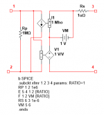
Hello jazbo8,
thank you. The Model Looks nice, but LTSpice says to me : unknown subcircuit .... I have testet it with the model in the lib Folder and with the model in the Folder where i store my asc-files. I think there is a lot i do not understand in LTSpice....
thank you. The Model Looks nice, but LTSpice says to me : unknown subcircuit .... I have testet it with the model in the lib Folder and with the model in the Folder where i store my asc-files. I think there is a lot i do not understand in LTSpice....
It's a symbol file, use Notepad, copy and paste the above code into a new file and save it as "OPT_PP.sym", move the file to the LTSpice symbol sub-directory as shown below (under Program Files on your C:\ drive):Hello jazbo8,
thank you. The Model Looks nice, but LTSpice says to me : unknown subcircuit .... I have testet it with the model in the lib Folder and with the model in the Folder where i store my asc-files. I think there is a lot i do not understand in LTSpice....
An externally hosted image should be here but it was not working when we last tested it.
Speaking of LTspice and center-tapped inductors (but not transformers)...
I have a pair of Tango TC60-15W inductors that I'd like to use in a circuit sim. These are 60H with a center tap.
If using the standard inductor symbol, do I simply put two 30H inductors in series (with the correct DCR for each) and call the junction of the two the center tap? Or should I also use the K directive and give them some mutual inductive coupling? They are on the same core, after all...
I hope this is within the scope of this thread. If not, let me know.
PS - The reason I ask is that in a circuit I'm looking at, using the inductor as plate loads for two triodes in push-pull, if I leave the two 30H series inductors uncoupled (no K directive) THD is like 0.2%. If I use the K directive to couple the two inductors, distortion from the triodes drops to 0.025% Which one is the more accurate representation?
thanks
Last edited:
Since both windings are on the same core, you have to use the K directive.If I use the K directive to couple the two inductors, distortion from the triodes drops to 0.025% Which one is the more accurate representation?
Thanks, that's what I figured, and that is *excellent* news for me! The circuit seems to be working very well with the K directive in place.
You may want to try the method shown by jackinnj above to see if you get the same result without using the K directive.
You may want to try the method shown by jackinnj above to see if you get the same result without using the K directive.
Do you mean this?
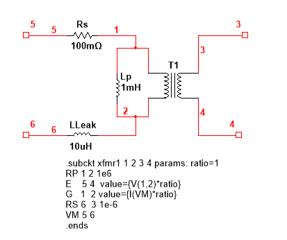
I'm afraid I wouldn't know where to start. For one thing, that's a single primary to single secondary. I'm not sure how I'd put a center tap and then add the external components (leakage L, parallel L, series R).
--
Dynaco Output Transformer SPICE Models
I've been looking for good models for the Dynaco ST-70 and Mark III output transformers for some time. These carried Dynaco part numbers A-470 and A-431 respectively. Dynaco didn't provide any technical specifications for these other than the reflected impedance, but Transcendar makes clones of these transformers and does specify the primary inductance and DC resistance for their offerings. See link below.
Push-Pull Transformers - Transcendar Audio Transformers
Can someone here produce LTspice models for either or both of these?
Thanks.
The equivalent circuit in post #880 has some errors, the one in #885 is correct, may be jackinnj will post an equivalent circuit and SPICE code for the tapped transformer later, in any case, it will be much more complicated...Do you mean this?
I'm afraid I wouldn't know where to start. For one thing, that's a single primary to single secondary. I'm not sure how I'd put a center tap and then add the external components (leakage L, parallel L, series R).
Last edited:
Last edited:
The equivalent circuit in post #880 has some errors, the one in #885 is correct, may be jackinnj will post an equivalent circuit and SPICE code for the tapped transformer later, in any case, it will be much more complicated...
I could take a readymade simulation and put it to use, but I'm afraid it's far beyond me to take jackinnj's basic transformer circuit and adapt it to be a CT choke.
From the imperfect model I have now, it's surprising to see the nice reduction in THD realized from using one. However, I also found that using the CT choke as plate loads for an LTP/phase splitter looks to have problems. There seems to be a flip in the frequency response from some kind of resonance. This only happens when using the LTP as a phase splitter. Give the same circuit a balanced input (make it a plain old differential amplifier) and that flip in the frequency response flattens out. Strange.
--
Yes, I've been using that set of models and they appear to work OK. But what I noticed for the Dynaco A-470 in particular is the large difference in primary inductance between the spreadsheet generated model and the inductance specified for the Transcendar clone. While the ratios between primary sections and secondary might be correct so that simulations work OK, I'm curious if a model based on actual physical characteristics might be more accurate.
Thank You again jazbo8. With a few modifikationes can i work with the PP Opt's using a pulldown menue. Great when LTSpice does what i will 😀
I'm afraid I wouldn't know where to start.
--
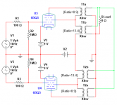
If it's an ultralinear transformer, you have two such units with their primaries connected in series and their secondaries in parallel. Here's a PP 6Bq5 example. Let's guess that the Z impedances are 4,000 and 8 ohms, for each such that the N ratio is SQRT(Zp/Zs)= 22.3. One primary Ratio is 13.4, the second is 8.9:
Attachments
But what I noticed for the Dynaco A-470 in particular is the large difference in primary inductance between the spreadsheet generated model and the inductance specified for the Transcendar clone.
diytube.com • View topic - Sanity check of A470 Output Xfmrs
"From my mid 70s Japanese Dynaco A470 (out of circuit, on my bench):
Measured with Wavetek Meterman 37XR:
Center Tap to front plate lead = 87 ohms
Center Tap to rear plate lead = 104 ohms
Center Tap to front screen lead = 29 ohms
Center Tap to rear screen lead = 34 ohms
I measure 10H from center tap to either plate connection."
- Home
- Amplifiers
- Tubes / Valves
- Vacuum Tube SPICE Models