cogsncogs, your formatting is much better. (!!)
So I guess the verdict is that AN's EL86/6CW5 model will suffice for 6P43P-E. That's great to know. Thanks!
--
So I guess the verdict is that AN's EL86/6CW5 model will suffice for 6P43P-E. That's great to know. Thanks!
--
Just a quick reminder - please DO NOT post any Ayumi model without the copyright information at the top of the code, this is the only condition Auymi stipulated for sharing his models, so please respect it.
Thanks jazbo8 for the heads up. I didn't know about the copyright stipulation. I wish I could remember where I found that model posted out there on the web.
If an Admin wants to delete the post with the offending code, please go right ahead. I believe it's this one:
http://www.diyaudio.com/forums/tubes-valves/243950-vacuum-tube-spice-models-92.html#post4348634
If an Admin wants to delete the post with the offending code, please go right ahead. I believe it's this one:
http://www.diyaudio.com/forums/tubes-valves/243950-vacuum-tube-spice-models-92.html#post4348634
 Ayumi model sans copyright information removed. Please make sure the copyright information is included - this is the only stipulation made by Ayumi for the public use of his algorithm and should be respected. Thanks!
EIMAC models?
Anyone got a model for 4-65, 4-125, 4-400 or equivalent tubes in triode or tetrode?
Thank you!
Anyone got a model for 4-65, 4-125, 4-400 or equivalent tubes in triode or tetrode?
Thank you!
Good luck finding them - their characteristics are quite different from the typical beam tetrodes.
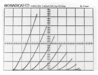
Hello jazbo8, I wonder do you have time to create a LTspice model for 6KY8a. I have the triode-connected curve for 6KY8a beam power section as shown below.
Your 6DS5 model worked great, I used it simulating a SE amp (using 6j6 as Voltage amp). I am going to build it as part of my Summer project. Thank you again!
Your 6DS5 model worked great, I used it simulating a SE amp (using 6j6 as Voltage amp). I am going to build it as part of my Summer project. Thank you again!
Attachments

6KY8A Pentode Section SPICE Model
Please be aware that this model was built using the triode-connected data that you provided, and it unfortunately did not match the pentode characteristic shown in the RCA datasheet, so bear that in mind when you use it.
Hello jazbo8, I wonder do you have time to create a LTspice model for 6KY8a. I have the triode-connected curve for 6KY8a beam power section as shown below.
Please be aware that this model was built using the triode-connected data that you provided, and it unfortunately did not match the pentode characteristic shown in the RCA datasheet, so bear that in mind when you use it.
Code:
*
* Generic pentode model: 6KY8_P_AN
* Copyright 2003--2008 by Ayumi Nakabayashi, All rights reserved.
* Version 3.10, Generated on Sat Jun 20 06:53:43 2015
*                 Plate
*                 | Screen Grid
*                 | |  Control Grid
*                 | |  |  Cathode
*                 | |  |  |
.SUBCKT 6KY8_P_AN A G2 G1 K
BGG   GG   0 V=V(G1,K)+1
BM1   M1   0 V=(0.095313333*(URAMP(V(G2,K))+1e-10))**-1.0989454
BM2   M2   0 V=(0.57715719*(URAMP(V(GG)+URAMP(V(G2,K))/4.4363448)))**2.5989454
BP    P    0 V=0.0031004553*(URAMP(V(GG)+URAMP(V(G2,K))/7.6865452))**1.5
BIK   IK   0 V=U(V(GG))*V(P)+(1-U(V(GG)))*0.0022026287*V(M1)*V(M2)
BIG   IG   0 V=0.0015502276*URAMP(V(G1,K))**1.5*(URAMP(V(G1,K))/(URAMP(V(A,K))+URAMP(V(G1,K)))*1.2+0.4)
BIK2  IK2  0 V=V(IK,IG)*(1-0.4*(EXP(-URAMP(V(A,K))/URAMP(V(G2,K))*15)-EXP(-15)))
BIG2T IG2T 0 V=V(IK2)*(0.85149976*(1-URAMP(V(A,K))/(URAMP(V(A,K))+10))**1.5+0.14850024)
BIK3  IK3  0 V=V(IK2)*(URAMP(V(A,K))+1500)/(URAMP(V(G2,K))+1500)
BIK4  IK4  0 V=V(IK3)-URAMP(V(IK3)-(0.0021745412*(URAMP(V(A,K))+URAMP(URAMP(V(G2,K))-URAMP(V(A,K))))**1.5))
BIP   IP   0 V=URAMP(V(IK4,IG2T)-URAMP(V(IK4,IG2T)-(0.0021745412*URAMP(V(A,K))**1.5)))
BIAK  A    K I=V(IP)+1e-10*V(A,K)
BIG2  G2   K I=URAMP(V(IK4,IP))
BIGK  G1   K I=V(IG)
* CAPS
CGA   G1  A  0.048p
CGK   G1  K  1.6p
C12   G1  G2 1p
CAK   A   K  0.3p
.ENDS
Last edited:
Please be aware that this model was built using the triode-connected data that you provided, and it unfortunately did not match the pentode characteristic shown in the RCA datasheet, so bear that in mind when you use it.
Hi jazbo8, thank you!
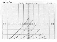
I have three sets of the triode-connected data here, would you please to check out which one can get better match with the RCA datasheet?
Thanks again!
Attachments
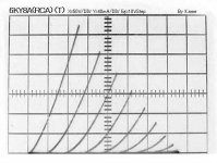
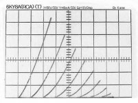
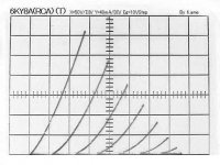
Unfortunately, none of them is close to the datasheet, the mis-matches are the greatest at higher bias voltages (Eg1 > -10V), the datasheet shows lower current than the samples. In any case, the tubes can work over a wide operating range, so the model that I provided should suffice for now until a better sample comes along.would you please to check out which one can get better match with the RCA datasheet?
Hello jazbo8, thank your so much for your helps!Unfortunately, none of them is close to the datasheet, the mis-matches are the greatest at higher bias voltages (Eg1 > -10V), the datasheet shows lower current than the samples. In any case, the tubes can work over a wide operating range, so the model that I provided should suffice for now until a better sample comes along.
I got the curves from this website "http://homepage2.nifty.com/Kame/6KY8Asyu.htm",
I simulated your model using "DC sweep" in LTspice, the results matched well with their Ip vs Vp curves (@Vsc=120V). Please see the attachments.
I also attached the curve of 6ky8 triode section, is the triode section the same as 12AT7 or similar?
Thanks again!
Attachments
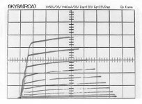
Good to see that the model matches up with the pentode characteristic on the Japanese site, since that was the sample used to build it in the first place (or close to it). Also the triode section appears to be very different from the 12AT7, not sure of what the closest equivalent might be...the results matched well with their Ip vs Vp curves (@Vsc=120V). Please see the attachments. I also attached the curve of 6ky8 triode section, is the triode section the same as 12AT7 or similar?
No, it's very different from 12AT7. A 6SL7 would appear to be the closest match with a slightly lower mu and Rp. Remember, you must take into consideration Rp and transconductance along with mu. 😉I also attached the curve of 6ky8 triode section, is the triode section the same as 12AT7 or similar?
6KY8A triode section LTspice model
6KY8A triode section model for LTspice.
6KY8A triode section model for LTspice.
Code:
* 6KY8AT LTSpice model
* Rydel model (5 parameters): mean fit error 0.150746mA
* Traced by Wayne Clay on 6/22/2015 using Engauge Digitizer and
* Curve Captor v0.9.1 from RCA datasheet.
.subckt 6KY8AT  P G K
    Bp  P K  I=
+ ((0.00144469087m)+(-0.0001050179892m)*V(G,K))*uramp((71.84993107)*
+ V(G,K)+V(P,K)+(62.44961062))**1.5 * V(P,K)/(V(P,K)+(3.613380107))
  Cgk G K 15.2p ; 0.2p added (15p, K+H)
  Cpk P K 7.2p ; 0.2p added (7.0p, K+H)
  Cgp G P 1.14p ; 0.7p added (0.44p)
  Rpk P K 1G ; to avoid floating nodes
  d3  G K dx1
.model dx1 d(is=1n rs=2k cjo=1pf N=1.5 tt=1n)
.ends 6KY8ATHello all,
Has anyone models of the tube rectifiers 6DL3 or 6D22s?
I only found one PSpice model from the 6D22S on duncan-amps. But i can not implement it in LTSpice..
Thank you all
Dieter
Has anyone models of the tube rectifiers 6DL3 or 6D22s?
I only found one PSpice model from the 6D22S on duncan-amps. But i can not implement it in LTSpice..
Thank you all
Dieter
You'll need the symbol (6d22s.asy) included in the zip file below. Extract the folder to your working directory.Hello all,
Has anyone models of the tube rectifiers 6DL3 or 6D22s?
I only found one PSpice model from the 6D22S on duncan-amps. But i can not implement it in LTSpice..
Thank you all
Dieter
Attachments
Sorry,
it does not work. The Symbol Need the tube.lib file. This is not in my System. Is there another model out?
Thanks for Help
Dieter
it does not work. The Symbol Need the tube.lib file. This is not in my System. Is there another model out?
Thanks for Help
Dieter
Sorry,
it does not work. The Symbol Need the tube.lib file. This is not in my System. Is there another model out?
Thanks for Help
Dieter
.model 6D22S D(Is=1e-2 RS=22 Cjo=12p vj=2 N=30 bv=5000 mfg=Svetlana type=vacuum )
copy this in: lib-cmp-D standard. Will work fine with SS diode symbol
Last edited:
- Home
- Amplifiers
- Tubes / Valves
- Vacuum Tube SPICE Models