Stick to the topic and stay away from personal remarks.
I agree, let's avoid the ego stuff, and let's look at the facts.
I, for one, would appreciate a fresh summary of what this "effect" is and isn't.
As far as I understand, it is a shunt capacitor between the inverting and non-inverting output of a PCM DAC, forming a low-pass filter with a corner frequency near 20 kHz, right?
Does it only work with current output, or does it work with voltage output too?
All been answered.
Go back, it's all there.
I am sure it is all there, but rather spread out. I do think it would be useful to have the facts summarized in one place, with a clear separation between the known facts and all the speculation and theories that have come up.
Edit: seems you edited your message while I was replying. I am thus kindly asking for a summary of the known facts, if possible.
Last edited:
Gentlemans some time I go I read this document but never tested. Proposal inside is somehow similar.
https://www.google.ro/url?sa=t&sour...F2BPVyTOUnbQiHkqQ&sig2=gZ7RRNAwS7rpsUt4I6MQwQ
https://www.google.ro/url?sa=t&sour...F2BPVyTOUnbQiHkqQ&sig2=gZ7RRNAwS7rpsUt4I6MQwQ
Gentlemans some time I go I read this document but never tested. Proposal inside is somehow similar.
https://www.google.ro/url?sa=t&sour...F2BPVyTOUnbQiHkqQ&sig2=gZ7RRNAwS7rpsUt4I6MQwQ
Thanks! It does actually go into the rationale in pretty good detail. So according to that document, the effect of the low pass filter capacitor is to cut the high level of HF noise associated with a PWM DAC (up to 20 dB at 350 kHz).
Any questions rendered in a respectful manner with get a respectful reply.
Let's really try to avoid issues of person and ego. This is about facts.
I do think it would be useful to have the facts summarized in one place, with a clear separation between the known facts and all the speculation and theories that have come up.
I am thus kindly asking for a summary of the known facts, if possible.
Any questions rendered in a respectful manner with get a respectful reply.
I asked for more details of the DAC in post #472 but so far haven't noticed a reply. Was my question deemed disrespectful?
Gentlemans some time I go I read this document but never tested. Proposal inside is somehow similar.
https://www.google.ro/url?sa=t&sour...F2BPVyTOUnbQiHkqQ&sig2=gZ7RRNAwS7rpsUt4I6MQwQ
Hi Adrian
It is NOT the same - very different indeed.
Please trust me on this, I am way ahead of that paper and we are dealing with something quite different.
For example, the "Rasmussen Effect" also works with a Zobel Network tuned in such a way as to have zero effect on high frequency noise, and a number of other experiments likewise confirms that high frequency noise is not at the core of this.
But I can see why it would be easy to think that way - accept...
Now for the schematic in that paper, let me point out why there is a significant difference.
Yes, indeed looks similar, except it isn't - that filter is too high in impedance to work on what is a "voltage" DAC.
Note the 10K? That should be reduced to 47-100R and then the cap (which will be hugely larger in value) needs to be tuned to get the desired response at 20KHz.
That 10K is effectively a buffer from the added cap in red, and indeed the two smaller caps to ground from the same point. The DAC "sees" the 10K, whereas the Rasmussen Effect it must "see" a low enough value that affects the output of the DAC directly. In that schematic below, the response change only occurs after the resistor, what we are inducing is a change on that DAC's output.
In effect a load in put on the DAC's output.
We have even tested this with a pure delta-sigma modulator output (it is basically an unfiltered "voltage" source), pure in the sense that it has no low-bit (typically 5 bit) manipulations, just the modulator only - and we were able to blind test a Zobel Network with near zero filtering above 100KHz. Consequently, filtering is not the issue. One former board member of a board that makes recommendations to Texas Instruments (Burr-Brown), when confronted with these facts and was demonstrated, he felt that there was something in the delta-sigma modulator that was being 'damped.'
If so, it needs to be looked at and I am humble enough to admit it, that I need help on that front, as d-s modulators are tricky things. One person I can think of that I would like to look at this is Martin Mallinson. He has that open mind and could tackle it.
Much of the above, I have referred to this earlier on - but again it needs to be read and hence I have been patient to repeat it again.
Cheers, Joe

Last edited:
For example, the "Rasmussen Effect" also works with a Zobel Network tuned in such a way as to have zero effect on high frequency noise, and a number of other experiments likewise confirms that high frequency noise is not at the core of this.
So with a resistor in series with the capacitor? What component values have you used?
So your theory is that it is the capacitive loading on the DAC output that is the relevant factor?The DAC "sees" the 10K, whereas the Rasmussen Effect it must "see" a low enough value that affects the output of the DAC directly.
Again, could you please let us know the component values you used, and the output impedance of the preceding DAC stage?We have even tested this with a pure delta-sigma modulator output, pure in the sense that it has no low-bit (typically 5 bit) manipulations, just the modulator only - and we were able to blind test a Zobel Network with near zero filtering above 100KHz.
I asked for more details of the DAC in post #472...
Could you be a little more specific and I would be only too happy - tell me the circuit configuration and I will tell you what we've found to be the correct implementation. A lot of work has gone into this, as we have to cover different ways in which designers decide to treat the DAC's out. Is it I/V, is it Current or voltage etc, passive I/V and so one.
All along I have been willing to be helpful. Let's just keep on topic and go through the issues as it is horses for courses.
A good start.
Cheers, Joe
.
this is lpf 😀
Not exactly, in some cases it has to be implemented with a Zobel Network which has no filtering of any note above 100KHz.
This is something we have looked at exhaustively before we could finally discount it. But it still gets repeated, so I will be patient.
Cheers, Joe
.
Hello Joe.
If I understand correctly, you are advocating adding a capacitance load directly across the dac balanced output lines such that a circa -1.5dB @ 20kHz drooping response is caused.
I well expect that (directly inaudibly for the most of us) rolling off the tops like this will reduce downstream IMD and other modulation audibly apparent effects.
Have you tried HF rolling off of preamp stages with the same/similar -1.5dB @ 20kHz and noted if the final loudspeaker resultant is similar/same ?.
Dan.
Let's really try to avoid issues of person and ego. This is about facts.
.
Julf, that would be great. That is what I have wanted all the time.
I do think it would be useful to have the facts summarized in one place, with a clear separation between the known facts and all the speculation and theories that have come up.
I am thus kindly asking for a summary of the known facts, if possible.
That summary would take a LOT of typing. And no speculation? When I speculate I say I speculate and when I don't speculate, it should be obvious. I will draw reasonable conclusions when the evidence takes me that way, but in no way am I ever going to make it dogma. That approach is counter-productive anyway.
Much of it has already been posted, but is difficult to assimilate - so yes, a summary is desirable, I can understand that. Indeed a friend of mine is in the process of setting up a website totally dedicated to this topic and all the pros and cons - but that is time consuming but it will happen.
Can you do me a favour, could you please read Ken's "summary" in post #21 as a starting point.
Next:
Give a circuit configuration we can discuss and then I could describe what approach to take in that particular instance, the ins and out of that situation. The next one then becomes easier. There are many variabilities to describe and this way we could start in a focused way.
I propose we take one configuration at a time, like chapters.
Give me a starting point - and once that is covered, go to the next one. That's like turning to the next page as there is no single page summary I can think of right this moment.
I have also received an email that says once person got this working with a couple of nF and that doesn't add up. So somebody is not doing it right, sigh. So the wrong implementation just means wrong data.
Finally, since a Zobel Network that flattens out above 100KHz, it is clear that we are talking about something that is lower in frequency and that is a mystery indeed.
Read Newton #21 and that would be a good start.
Cheers, Joe
.
Hello Joe.
If I understand correctly, you are advocating adding a capacitance load directly across the dac balanced output lines such that a circa -1.5dB @ 20kHz drooping response is caused.
I well expect that (directly inaudibly for the most of us) rolling off the tops...
Dan.
Hi Dan
How is WA?
Check out my post #461.
Of course nobody is saying that being -xdB at 20KHz is a desirable thing. No way.
Various methods exists, some I have pointed to in past posts, where the flat response can be recovered elsewhere, but it must be buffered away from the pins of the DAC's output.
If you are using a USB DAC, then I have furnished actual data of how to recover flat frequency response in JRiver - and indeed we have A-B'd the roll-off using JRiver and certainly you can hear it some source material, no surprises there.
If you also go back, I have suggested that the response of the d-s DAC's output could be found where it sounds best and then corrected. What is suggested here is that the DAC does not sound at its best when flat at that point. Get flatness back elsewhere and you are cooking.
Then I have used the suggested schematic of Burr-Brown's PCM1794A and shown how the response that the DAC's pins can be altered and yet adding two 12n capacitors after the I/V stage and you have covered the flat response. Voila, mission accomplished.
We are looking at various ways to recover the flat response, in no way are we preaching that the wrong response sounds better.
But the above is really only a side issue and a distraction about what this really is about:
Why does altering the frequency response make a difference to the sound of a delta-sigma outputs? It is now clear that such a flat response is not when it sounds at its best.
THAT is what this is all about.
Is this making sense? I have tried to point out the above repeatedly, but making only some progress and others think it is just to silly to take it seriously.
BTW, my phone number is on my website and everybody knows it, so I might as well ask if you want to call me for a chat on 0412-203382 and you can ask as many questions you like and the harder the better. I am not trying to pull wool down... whatever.
If you call me, it will also give my fingers a rest from a lot of typing that I have done just today.
Cheers, Joe
02-96074650 & 0412-203382
Joe Rasmussen Pages
.
Last edited:
So with a resistor in series with the capacitor? What component values have you used?
So your theory is that it is the capacitive loading on the DAC output that is the relevant factor?
Again, could you please let us know the component values you used, and the output impedance of the preceding DAC stage?
I have given this some serious thought and I believe I can give you everything you want.
Five Scenarios:
1."Current" DAC into standard Virtual Earth, with ALL values supplied.
2. "Current" DAC into Low Impedance Passive I/V, with ALL values supplied.
3. "Current DAC into Step-Up Transformers - with projected and approximate values supplied (have to be calculated individually).
4. "Voltage" DAC into regular Opamp Circuit that sums the the two phases, with projected and approximate values supplied (have to be calculated individually).
5. "Voltage" DAC into 1:1 Transformer - with projected and approximate values supplied (have to be calculated individually).
I think covering them one by one will give us the pros and cons and also exchange of views, questions etc.
Please give time and be patient as I set forward each, one by one.
_____________________________________________________________________
Now I have work to do as I will present first scenario:
1."Current" DAC into standard Virtual Earth, with ALL values supplied.
Cheers, Joe
Last edited:
Hi Mr Joe Rasmussen
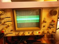
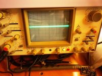
here is my output wave about 30-50mv ripple before put LPF filter on output of my DAC ESS9018K2M Diyhnk
and after 1-2mv with filter .
Which is your suggestion for this dac with one opamp?
here is my output wave about 30-50mv ripple before put LPF filter on output of my DAC ESS9018K2M Diyhnk
and after 1-2mv with filter .
Which is your suggestion for this dac with one opamp?
Attachments

Hi Mr Joe Rasmussen
here is my output wave about 30-50mv ripple before put LPF filter on output of my DAC ESS9018K2M Diyhnk
and after 1-2mv with filter .
Which is your suggestion for this dac with one opamp?
Thanks for your cordial approach, but I am just plain ol' Joe.
I will be addressing your situ as Scenario 1 shortly. This is arguably the typical implementation and in this instance the ES9018 is used in current mode into a Virtual Earth. It can of course also be used in "voltage" mode and we shall get to that in Scenario 4. So we shall revisit ES9018 twice.
A filter is always a filter, all things being equal, and that is what we see on your scope, but later in Scenario 5 we end up not using a filter, but a Zobel Network, where a 1:1 transformer does the job of filtering HF>100KHz. The reason for pointing this out is to consider that we are not really talking about a filter perse' because the "Rasmussen Effect" can be triggered by something that is not a filter as such, but, as we shall see, an over-cooked Zobel that does nothing above 100KHz. Sometimes we may use a proper filter, but in other cases it will be a Zobel.
So all this will unfold. Scenario 1 coming up first.
Cheers, Joe
.
Hi 🙂
I spot the effect too...
This is more emphasized with newer dac types, then older ones.
And I am think that some kind of filtering should be placed.
.
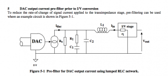
Some authors suggesting filtering.
Malcolm Hawksford in article
C111 Current steering transimpedance amplifier.pdf
Malcolm John Hawksford - Publications
presentss an idea of, he said, pre-filter for Iout Dacs
(but without values of the elements only like a concept sketch)
.
I spot the effect too...
This is more emphasized with newer dac types, then older ones.
And I am think that some kind of filtering should be placed.
.
Some authors suggesting filtering.
Malcolm Hawksford in article
C111 Current steering transimpedance amplifier.pdf
Malcolm John Hawksford - Publications
presentss an idea of, he said, pre-filter for Iout Dacs
(but without values of the elements only like a concept sketch)
.
Attachments
Some authors suggesting filtering.
Malcolm Hawksford in article
C111 Current steering transimpedance amplifier.pdf
Malcolm John Hawksford - Publications
presentss an idea of, he said, pre-filter for Iout Dacs
(but without values of the elements only like a concept sketch)
.
Interesting, as he seems to have both a zobel circuit and a LCR filter. Which paper is that from?
You have a link...
C111 Current steering transimpedance amplifier.pdf
actually it could be derived and simulated with steps
1. just C parallel with Riv - have almost always peek at the cut-off starting point
2. C with RC damping network slight reduced peek, but not at all
3. L faltering the around the Fo point.
.
It is not issue to have desired rolloff at the Fhigh
But it is not easy to get minimum phase shift?
.
Last edited:
- Status
- Not open for further replies.
- Home
- Member Areas
- The Lounge
- DAC Filtering - the "Rasmussen Effect"