You have a link...
Unfortunately the link points to the list of all his 208 publications, and the specific one you mention doesn't seem to be available.
Thanks! Very interesting paper, will have to do some simulations.
Hi 🙂
I spot the effect too...
This is more emphasized with newer dac types, then older ones.
And I am think that some kind of filtering should be placed.
It has no beneficial effect on R2R/ladder DACs - all now considered obselete, but as we know still have supporters.
Some authors suggesting filtering.
Malcolm Hawksford in article
C111 Current steering transimpedance amplifier.pdf...
Malcolm Omar Hawksford is somebody I have only the hoghest regard anbd a real gentleman and generous to boost. We at Vacuum State and the late Allen Wright had contact with him and his paper re cable geometry which Hawksford approved Allen to include in his SuperCables Cooikbook - where based on conversations with him, Allen was able to add an explanatory chapter, in language far more accessible to rest of us, called Concepts. A lot of cable hum-bug dispensed with. If you can get a copy of the book, well worthwhile hunting down. Been thinking about making it available as a PDF file.
Hi 🙂
presents an idea of, he said, pre-filter for Iout Dacs
(but without values of the elements only like a concept sketch)
.
Very interesting. But what is curious is that the 'effect' also behaves the same for Vout and not just Iout, so go figure?
I will cover that in Scenario 4. with Vout DACs.
Now I would like to make the simple point, even if we find that the outputs performs best (audible to everybody in the room) when the response is not flat at 20KHz, that does not mean we cannot have a flat response on the final output.
Brian Gurr in New Zealand, I asked him to independently to very the degree of being -2dB and flat at 20KHz and he said it was audible, but depending on instruments being replayed. He did this by using JRiver's 64 bit Parametric Eqializer and the settings I gave in post #461 - these will ensure flat response.
Cheers, Joe
.
Yes You are right... 🙂
This effect is even more, as I could spot from diferent dac chips, present with Vout types.
With note to delta sigma ones.
.
Some datas showing that older r2r types have alreadu roll-off of 1db cca to 20K
BUT only with no oversampling? * jpeg
.
You will be probably laughing, 😎
but now I am listening old TDA1540D, 14bit, good old ceramic package
dac type, dual mono, CPLD packed input format digital input bus. Riv=10ohm
.
Also I have one dac with Wolfson WM8740. Guess which one have "Rasmussen effect". Both simple SE JFET output. No OP amps...
.
And I am preparing to try "C" @ Wolfson diff outputs like You suggest.
.
One more note, for me it is almost impossible to listen unfiltered kind of dacs
with horns, also I spot that is very hard to obtain solid crossover point and values, even with measurements monitoring, when outputs are unfiltered?
This effect moving down to 1K or more, I think... 🙂
Attachments
Please be patient with me, I am suffering from an infection right now and have a mild temp and on anti-biotics - so we will attend to Scenario 1 as soon as possible.
I am hoping that from that point on we can have a cordial and respectful conversation and any question that may be asked in that spirit, ask away and I will do my best.
.
I am hoping that from that point on we can have a cordial and respectful conversation and any question that may be asked in that spirit, ask away and I will do my best.
.
Hi 🙂...Some authors suggesting filtering.
Malcolm Hawksford in article
C111 Current steering transimpedance amplifier.pdf
Malcolm John Hawksford - Publications
presentss an idea of, he said, pre-filter for Iout Dacs
(but without values of the elements only like a concept sketch)
.
The effective distortion equivalence of transimpedance stage slewing error and sample clock jitter is an very significant point that Prof. Hawksford mathematically analyzes in this paper. Slewing error has the potential to be far more problematic than sample clock jitter, I think, for the following two reasons. First, slewing error would have the same effect as code dependent clock jitter. Both would non-linearly alter sample energy (area) as a funtion of sample amplitude, which then makes either effect undesirably correlate with the signal, however, not all clock jitter is code deterministic. Second, as others have pointed out elsewhere, sample clock jitter error magnitude is typically measured in picoseconds, while I/V slewing error magnitude might typically be measured in units of time several orders of magnitude greater. Which means the consequences of slewing error could be severa orders of magnitude greater than that of clock jitter.
Last edited:
I just discovered this thread a few days ago.
Fortunately, I have an old (1997) unused Sony surround processor that has a very similar circuit configuration to that in post #202. There was nothing to lose by modding it.
This Sony processor also has a bypass input that easily allows it to be compared with an external DAC/source. So I "Rassed" it and compared with my current DAC, a Cambridge DacMagic. I level matched it with the Sony and switched between them with the bypass feature.
After a couple hours of switching back and forth in real time, I thought that the Sony did a better job of presenting low level detail. It made instruments sound more like real instruments playing in the room and less like a reproduction.
Is this a purely subjective and anecdotal data point? Yes. I have no measurements to prove any difference between the two units. Do I know that the modification improved the Sony unit? No. For all I know, the mod made it sound worse.
What I do know is the Sony is my new source. The impression of increased resolution and ambience has continued through hours of listening. So if it is a a delusion, at least it is a persistent one.
My two cents. If you can try it as conveniently as I did, do it.
The effective distortion equivalence of transimpedance stage slewing error and sample clock jitter is an very significant point that Prof. Hawksford mathematically analyzes in this paper. Slewing error has the potential to be far more problematic than sample clock jitter, I think, for the following two reasons. First, slewing error would have the same effect as code dependent clock jitter. Both would non-linearly alter sample energy (area) as a funtion of sample amplitude, which then makes either effect undesirably correlate with the signal, however, not all clock jitter is code deterministic. Second, as others have pointed out elsewhere, sample clock jitter error magnitude is typically measured in picoseconds, while I/V slewing error magnitude might typically be measured in units of time several orders of magnitude greater. Which means the consequences of slewing error could be severa orders of magnitude greater than that of clock jitter.
I agree. So how much effect on slewing error do you think Joe's capacitor has? Seems it approximates one of the Hawksford topologies.
I agree. So how much effect on slewing error do you think Joe's capacitor has? Seems it approximates one of the Hawksford topologies.
Reduces any error, as far as the I/V circuit is concerned. Obviously, there are too many system specific variables to quantify a single general benefit. Hawksford's paper shows an example for an op-amp based transimpedance stage, however, any error reduction also depends on the parameters of the op-amp(s), and on the stage topology employed.
I think it's quite eye opening to realize the equivalence of the damage between slewing error and clock jitter, as well as how much greater can be the magnitude of the sample distortion resulting from slewing error versus clock jitter error.
\So if it is a a delusion, at least it is a persistent one.
Some delusions are better than others. 😉
.
Reduces any error, as far as the I/V circuit is concerned... I think it's quite eye opening to realize the equivalence of the damage between slewing error and clock jitter, as well as how much greater can be the magnitude of the sample distortion resulting from slewing error versus clock jitter error.
Ken, you help me think as your expertise is welcome.
Read through Hawksford's article, pretty complex but still able to get quite a bit out of it. Some of it reminds me of Charlie Hansen saying similarly that slewing post-DAC was a major cause of 'digital' sound and not just clock jitter and now Hawkford makes a correlation with jitter - and that it is related to opamp open loop being exposed makes sense. That is why he, Charlie Hansen, uses an zero-feedback OTA and buffer, and that must mean that he uses some kind of low Z passive I/V. This has been our approach as well, the late Allen Wright and Vacuum State. Low Z passive I/V and no feedback.
Now Ken, I have a few things to run past you:
Gradually things are emerging, that the 'effect' - or rather treating it - does not rely on a low-pass filter, indeed you can add some series resistance to the cap across the DAC's phases, make it a Zobel, and you will still hear the benefits. Yet there is little filtering above 100KHz where the Zobel just levels off - so we have pretty much eliminated that the change in sound is due to slewing or filtering in the normal sense of the word (a Zobel can of course be over-cooked and shape the response, but then gets out of the way at HF). Besides, it has a positive effect and no slewing ever will.
This is Zobel'ing and not a filter'ing. 😀
Another thing has emerged, we got our hands on a pure delta-sigma DAC with no low-bit manipulation, just straight unprocessed 2.8xMHz - added a Zobel and it was very obvious to a number of people in the room - and it was a high performance system and oh boy, did the sound change.
Really, it all points to something in the delta-sigma modulator itself. We need to think Zobel network and analyse the effect it has on the DAC. (It also seems to eliminate integrator/integration of pulses as the cause as Barbera suggested earlier). I think it is about creating a load at some critical frequency band, and loading leads to the thought of damping.
And it points to things happening below 100KHz.
Even when there is no noise shaping/processing up around 70-80KHz. The DAC we tried it on eschews that.
Cheers, Joe
.
Joe, that sounds very promising to me - that the capacitor is allowing current to flow through the DAC in a fashion which improves its behaviour.I think it is about creating a load at some critical frequency band, and loading leads to the thought of damping.
My personal technique is to "thrash" the S-D DAC - force it to decode high level, high frequency audio data over an extended period - this always causes the sound to change, improve. The big downside is that this has to be done every time, from cold - no permanent conditioning takes place.
...Gradually things are emerging, that the 'effect' - or rather treating it - does not rely on a low-pass filter, indeed you can add some series resistance to the cap across the DAC's phases, make it a Zobel, and you will still hear the benefits.
That then supports my thinking on this up to now, as I've recently suspected that your initial reaction way back when, that the effect reminded you of how the sound improves once an MC phono cartridge is properly loaded, was close to the truth. Perhaps, typical SDM DAC chip outputs can be rather reactive at high frequencies, therby forming an underdamped resonant circuit with the I/V stage parasitic reactive elements. In addition, DAC output reactance may be code dependent, making the parasitic output reactance appear to be modulated in a non-linear fashion by the signal. If true, then placing a relatively large capacitance across the outputs may simply be swamping any smaller non-linear DAC chip output capacitance. However, that's just conjecture.
I agree that effect doesn't appear to be due to marginally increased ultrasonic noise filtering, and is instead, likely time domian related. If the problem with DSM DACs is due, however, to code dependent modulation of parasitic output capacitance, that might explain why both voltage and current output DACs respond to loading, but that's not yet clear to me.
Another thing has emerged, we got our hands on a pure delta-sigma DAC with no low-bit manipulation, just straight unprocessed 2.8xMHz - added a Zobel and it was very obvious to a number of people in the room - and it was a high performance system and oh boy, did the sound change.
That then would eliminate the sort of slewing distortion presented by Prof. Hawksford in his paper. I don't think that 1-bit conversion, such as DSD, can exhibit the differential phase error that can be produced by multi-bit conversion. With only two possible valid states, 1-bit conversion is inherently linear - as two points define a straight line. So, even if the system exhibits slewing error, that error becomes a constant, and so, is a linear distortion. In addition, 1-bit conversion should not be subject to code dependent modulation of DAC parasitic ouput reactance since there are only two codes, one and zero. Also, I've no idea how the presence or absence of noise-shaping might be affecting the effect, particularly, if ultrasonic noise filtering truly isn't a factor. Please keep us up to date on your interesting investigation of the raw sigma-delta-modulator DAC with Zobel loading.
By the way, what values of R and C are you finding works well for Zobel/Snubber with common SDM DAC chips.
Last edited:
Hi
the 2 options is coming out
1. applying the filtering network direct @ dac output, loading with the reactive elements dac output or outputs...
.
2. "buffering" the dac output, leaving the dac output without reactive loads AND apply filter after, knowing more precise internal impedance of that sources and output net termination loads
.
Perhaps, typical SDM DAC chip outputs can be rather reactive at high frequencies, thereby forming an underdamped resonant circuit with the I/V stage parasitic reactive elements...
You bring up a number of things and while some may be conjecture, they are not baseless. But it is important to air these and get viewpoints.
Agree re Hawksford's slewing article (as good as he is to read), it isn't quite applicable, for an interesting reason, lifting the Virtual Earth makes the cap part of a Zobel network and I was able to plot it. Again, it is not a proper 1st order low-pass. I am almost ready to post that as part of Scenario 1 as promised.
Also, I've no idea how the presence or absence of noise-shaping might be affecting the effect, particularly, if ultrasonic noise filtering truly isn't a factor.
Gradually a picture is emerging - and yes, access to that RAW DSD DAC was so important I drove a round trip of nearly two thousand kilometres. I will later be able to give more details about this DAC, but there are sensitive reasons for not saying too much right now. It has no actual processing other integer multiplication of sample frequencies once converted to 1-bit and with a passive output stage - we just added a Zobel right on the output. But I am not a digital guy (but I am learning fast) and I defer to you gladly - but this is definitely a kind of detective work and like a dog with a bone... if you know what I mean. 😀
But, when you really think about it, the digital part is really the 'content', right? The code. But processing involves analog waveforms, voltage and current, that can behave and misbehave in so many ways. The code/content is digital, but the processing takes place in an analog world. What do you think?
By the way, what values of R and C are you finding works well for Zobel/Snubber with common SDM DAC chips.
Yes, values and all is coming up. And the different scenarios I will present one by one, all adds up to a consistent picture. BTW, one other highly regarded technician (hi Rodney) who has served on boards advising Texas Instruments, he brought up the 'damping' word without any soliciting on my behalf.
Cheers, Joe
.
OK, here goes. I admit to a slight nervousness...
1."Current" DAC into standard Virtual Earth, with ALL values supplied.
I gave some thought as to what Iout DAC to use, was thinking of ES9018 and their recommended post-DAC schematic (and I did model/plot it), but decided to go with Burr-Brown PCM1794A as it is a pure "current" DAC and the Sabre is not.
Added components. The values in Red are not part of the original recommended post-DAC circuit.
We are adding three components between the output(s) of the DAC and the input/virtual earth (ignore 0R ? as it was used for experimental purposes).
The output of the I/V converter is low Z and hence the compensation/EQ is suitably buffered. The two capacitors 12nF needs to be tweaked just right and will restore flat response at 20KHz, fully isolated from our post-DAC passive network.
Now we get to something interesting, that 1uF cap directly across the phases is in fact not quite a low-pass filter.
This was confirmed by plotting:
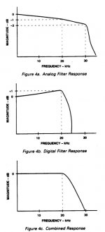
1. The final fully comepensated (what you end up listening to) response.
2. The inter-stage output of the I/V converter (no compensation yet applied).
3. And the actual residual voltage on the DAC output (compensated +49.6B to match the other two).
That last one looks like what?
It looks like a Zobel.
It also confirms that the filtering is gradually petering out above 100KHz and flatlining.
Our 'filter' cap is before the pair of 3R3 and as they are in series returning to ground, it becomes a Zobel. At some point the reactance of the cap becomes less than 3R3 and that happens below 100KHz. Above that we will get a plateau - no actual low-pass.
Same goes for what I did to that RAW DSD DAC in Queensland, it was a Zobel network of 15nF and 1K5, put some resistance in front of it and I get virtually the same slope. Guess what, by 100KHz that 1nF cap, relative to 1K5, gets out of the way.
I think we can definitely say we are not dealing with the effects of a low-pass filter and the 'effect' is actually, relatively speaking, low in frequency.
Tools:
I used CircuitMaker to test the above circuit and used SoundEasy V17 to plot the above.
OK, I hope that nobody thinks I have put my head on a chopping block posting above.
Next Scenario:
3. "Current DAC into Step-Up Transformers - with projected and approximate values supplied (have to be calculated individually).
Cheers, Joe
.
1."Current" DAC into standard Virtual Earth, with ALL values supplied.
I gave some thought as to what Iout DAC to use, was thinking of ES9018 and their recommended post-DAC schematic (and I did model/plot it), but decided to go with Burr-Brown PCM1794A as it is a pure "current" DAC and the Sabre is not.
Added components. The values in Red are not part of the original recommended post-DAC circuit.
We are adding three components between the output(s) of the DAC and the input/virtual earth (ignore 0R ? as it was used for experimental purposes).
The output of the I/V converter is low Z and hence the compensation/EQ is suitably buffered. The two capacitors 12nF needs to be tweaked just right and will restore flat response at 20KHz, fully isolated from our post-DAC passive network.
Now we get to something interesting, that 1uF cap directly across the phases is in fact not quite a low-pass filter.
This was confirmed by plotting:
1. The final fully comepensated (what you end up listening to) response.
2. The inter-stage output of the I/V converter (no compensation yet applied).
3. And the actual residual voltage on the DAC output (compensated +49.6B to match the other two).
That last one looks like what?
It looks like a Zobel.
It also confirms that the filtering is gradually petering out above 100KHz and flatlining.
Our 'filter' cap is before the pair of 3R3 and as they are in series returning to ground, it becomes a Zobel. At some point the reactance of the cap becomes less than 3R3 and that happens below 100KHz. Above that we will get a plateau - no actual low-pass.
Same goes for what I did to that RAW DSD DAC in Queensland, it was a Zobel network of 15nF and 1K5, put some resistance in front of it and I get virtually the same slope. Guess what, by 100KHz that 1nF cap, relative to 1K5, gets out of the way.
I think we can definitely say we are not dealing with the effects of a low-pass filter and the 'effect' is actually, relatively speaking, low in frequency.
Tools:
I used CircuitMaker to test the above circuit and used SoundEasy V17 to plot the above.
OK, I hope that nobody thinks I have put my head on a chopping block posting above.
Next Scenario:
3. "Current DAC into Step-Up Transformers - with projected and approximate values supplied (have to be calculated individually).
Cheers, Joe
.
Last edited:
This morning I tried a simple C (10nF value I have near hands...)
in parallel with Riv @ nos mode, TDA1540D Iotput. Because I left it removable, just add parallel C at the pins and put back in place...
I can say that the effect are significant. It is removed a sort of curtain of hissing
simillar to horn directivity effect. Also clear a bit the center mid.
Voices and sibilants are remain with reverbs and space present at the recordings.
I listened to different ages recordings and it was pretty much the same in terms of removing noise curtain letting the more "air" to the listening room...
Even I did not change the values of the crossover, still is the same
I have no doubt that it is like the same crossover doing better job...
...
🙂
Latter I will try to make some measurements
cheers
Its not quite as simple as that. The 'virtual ground' at the opamp inputs is not actually ground but a parallel combination of inductance and capacitance*. The inductance comes from the 750R feedback resistor and the resistance from the 2.2nF feedback resistor, both modified by the opamp gain (both phase and magnitude). The net result at 10's or 100's of kHz is likely to be mainly inductive, so this will result in a heavily damped parallel resonance with the 1uF cap. Not a pure low pass filter, as you say, but quite capable of modifying the level of HF entering the opamp and so affecting any slew rate problems. Interestingly, it is possible for the resonance to increase the problem if the damping is insufficient.Joe Rasmussen said:Our 'filter' cap is before the pair of 3R3 and as they are in series returning to ground, it becomes a Zobel. At some point the reactance of the cap becomes less than 3R3 and that happens below 100KHz. Above that we will get a plateau - no actual low-pass.
I'm not sure what you mean by 'Zobel'. I think of that as meaning a CR series but here they are in parallel, although with the R modified by the virtual ground inductance.
* You don't say which opamp you modelled, but taking a wild guess that the unity gain bandwidth might be 50Mhz I calculate the 'virtual ground' to look like 2.4uH in parallel with 1.45R.
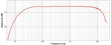
Hi this is the graph of the 10Riv (with JFET 2mA current injetion) + C=100nF
in parallel. Simple passive IV prior to the JFET amplifier and buffer stage.
No Riv+C only.
It is about -1 to -1.1 db @ 20KHz from 1KHz. So it should be little bit larger value to meet the -1.4db. The phase @ 20KHz is -3.6 to -4 deg from 1KHz.
Group delay is 4.86 mS 1k, 4.96mS 20k.
But I measured also significant distortion starting rapidly at 5K cca to 10Kcca...
Attachments
Last edited:
- Status
- Not open for further replies.
- Home
- Member Areas
- The Lounge
- DAC Filtering - the "Rasmussen Effect"