Enjoyed our discussion on the phone the other day.
Cheers, Joe.
Likewise.
It would be interesting to continue on from where we left off.
Dan.
On the home stretch and one of my favourite solutions.
5. "Voltage" DAC into 1:1 Transformer - with projected and approximate values supplied (have to be calculated individually).
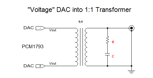
Again I can only give you an idea of the values of R and C, which of course (again) forms a Zobel.
Again, based on the transformer you choose, the one I use for the most part give me 15nF and somewhere around 1K2 to 1K5. Tweak resistor value to give you -2dB at 20KHz. You may of course test the transformer by driving it from a Sig Gen with low output Z, say 50 Ohm - and plot response up to 100KHz. You will not see any leveling off as per earlier Scenarios, as by 100KHz the transformer should be filtering enough to prevent you seeing it.
Many "voltage" DACs will give you near the full desired 2V RMS out -but the example above being PCM1793 will give you 1.15V RMS.
I would not recommend using this with the Sabre DAC. These transformers works best when driven from a low source Z and the Sabre is just too high, even with paralleled phases.
Again, it is not the Zobel that ultimately does the filtering, it is of course the transformer (band-pass), once we get high enough in frequency, the Zobel has little or no consequential effect.
And that completes the FIVE scenarios I promised.
There really is no excuse for anybody seriously into DIY for not implementing one of the above posted scenarios and then make appropriate comments.
I have done my bit, the rest of you will prove to be doers or non-doers. Never been a better time to hold the correct end of your soldering iron.
THIS IS DIY !!! - 😀😀😀
Cheers, Joe
.
5. "Voltage" DAC into 1:1 Transformer - with projected and approximate values supplied (have to be calculated individually).
Again I can only give you an idea of the values of R and C, which of course (again) forms a Zobel.
Again, based on the transformer you choose, the one I use for the most part give me 15nF and somewhere around 1K2 to 1K5. Tweak resistor value to give you -2dB at 20KHz. You may of course test the transformer by driving it from a Sig Gen with low output Z, say 50 Ohm - and plot response up to 100KHz. You will not see any leveling off as per earlier Scenarios, as by 100KHz the transformer should be filtering enough to prevent you seeing it.
Many "voltage" DACs will give you near the full desired 2V RMS out -but the example above being PCM1793 will give you 1.15V RMS.
I would not recommend using this with the Sabre DAC. These transformers works best when driven from a low source Z and the Sabre is just too high, even with paralleled phases.
Again, it is not the Zobel that ultimately does the filtering, it is of course the transformer (band-pass), once we get high enough in frequency, the Zobel has little or no consequential effect.
And that completes the FIVE scenarios I promised.
There really is no excuse for anybody seriously into DIY for not implementing one of the above posted scenarios and then make appropriate comments.
I have done my bit, the rest of you will prove to be doers or non-doers. Never been a better time to hold the correct end of your soldering iron.
THIS IS DIY !!! - 😀😀😀
Cheers, Joe
.
referring to post #560
I measured only Riv without parallel C. And this distortion was the same.
So that is not coming from the added C.
Also I add the pot. The distortion did not shown in that case. Only without pot
and with pot at max value. I don't know why at the moment I have to recheck
output circuit again. The output stage is terminated with 470K at end of JFET buffer, and
without any DC component. Adjusted to 0mV. I will try to add 100R after that to RCAs...
So everything is OK.
I mesure this using mac minis line input which is already BW limited and not suitable enough for higher F measurements. Also I used the Fuzzmeasure loudspeaker test software and i cannot find option to load condenser mic compensation data file?
So that measurements is not valid. Just a slight prewiev... 🙂
.
I simulated the circuit, and find that Value of 200nF cca suits about -1.35 db at 20K.
With large tolerance of Isource internal equivalen resistances...
Now I am using on TDA1540D 10ohm Riv -0.5mV offset at Iout pin
C=220nF
.
The sound is very good, with passive LDR pot and with passive Step up Transformer as well. Like "preamp"...
cheers 🙂
.
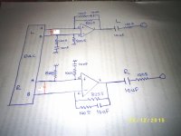
Hi Joe
Here is exactly the data sheet with double opamp OPA2134
maybe the capacitors 10nf in all section must be wrong value .I measure it on board the meter gives me 0,01 uf.
Look at the picture ,I put 4,7 nf is this correct?
What kind capacitor must use COG ,MKT.MKP?
Here is exactly the data sheet with double opamp OPA2134
maybe the capacitors 10nf in all section must be wrong value .I measure it on board the meter gives me 0,01 uf.
Look at the picture ,I put 4,7 nf is this correct?
What kind capacitor must use COG ,MKT.MKP?
Attachments
Last edited:
Hi Joe.
Thanks for the contributing more in this issue 🙂
I apreaciate Your research even personaly, I am not the fan in OP amps stages... 🙂
I prefer Single Ended, Non-complementary topologies.
.
I saw the example with Riv and Transformer at the output of the dac.
Because I have an experiance with such topologies, I can kindly point
that solution should be reconsidered.
The Thermogen resistance of primary layer act like another, parallel Riv with
basic Riv resistor. So the amount of current is "doing" to voltage trough this DC resistance. Base on this the value of this primary windings resistance is of main importance.
Another thing is that in that case dca chip loaded with Riv acts like driver of reactive load. That deserves very low internal impedance. Because it is highly reactive load.
From primary side, stronger value of primary inductance is needed to acheive low end
without phase shift. That means higher number of turns.
If it is step up, like in example shown, another thing is that we will have much more capacitance at the secondary. this capacitances are transferring with square to primary and directly to dac output pin load.
So in that case we load the dac chip with a significant Inductances, and maybe more with capacitances. All in all huge reactive load among basic Riv, which is in that case far from pure resistive nature.
.
I think that In case of using Riv, after I to V conversion, should be used a buffer with low internal impedance to properly drive interstage transformer.
After this, applying correct RC anti-ringing network like You suggest is next thing.
It is more valid to accomplish with analog generator of square signal of 10KHz to 20Khz
direct to the buffer driver of the transformer, and then empirically determine the RC damping network at the secondary. Because the load impedance is low and constant and will remain still with the dac as source...
.
I didn't mean to criticize just giving my point of view and note on this issue.
I feel that it would be very helpful if one first performs the experiment to confirm for themself whether they do or don't hear the effect being discussed. If one doesn't perceive the effect, then I doubt that a productive discussion can be had as to possible cause. The needed modification is rediculously easy to perform.
I feel that it would be very helpful if one first performs the experiment to confirm for themself whether they do or don't hear the effect being discussed.
Yep!
If one doesn't perceive the effect, then I doubt that a productive discussion can be had as to possible cause. The needed modification is ridiculously easy to perform.
Yep!
As the Staff Sergeant would holler to the troops:
"Stand to attention. Present your soldering irons." 😀
Cheers, Joe
.
Hi Joe
Here is exactly the data sheet with double opamp OPA2134
maybe the capacitors 10nf in all section must be wrong value .I measure it on board the meter gives me 0,01 uf.
Look at the picture ,I put 4,7 nf is this correct?
What kind capacitor must use COG ,MKT.MKP?
Can't answer all your questions, but that actual schematic, I have modified it and uploaded it and should be visible below.
You can add correction caps across R1, R2, R3 and R4, but I would suggest you don't bother unless you know what you are doing, wrong value and you could end up with an excessive rising response. So add the components shown and take a listen.
Cheers, Joe
.
Attachments
@ Ken post #589 🙂
Yes Ken You right, it is not complicated to try. I did and I "found" that it is something really going on about this effect. Actually I new before this topic, but this topic somehow
triggered me to go to try it. Thanks 🙂.
.
But one more thing, I did it because I have DIY example in-front my hands, and it was for me easy to perform this 2 minutes soldering test. As i mentioned I have open device, with modular IV resistor, just disconect R and solder parallel C...
Someone else probably have to open device, check out with the schematics, to find place to intervent, make intervention on the PCB, (not reversibile...) and prepare place with some connector for taking experimental more values...
It is simple in concpt - but not so simple to prepare?
.
cheers
🙂
 More off topic posts removed.
Final Warning. Stay strictly on topic and away from personal remarks. Failure to do so will find the offenders in Read Only mode.
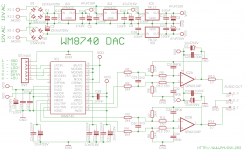
I spot that PCM1794A in focus.
When I look at the datasheet I found some pins that might be from importance.
These are VcomL, VcomR and Icom pins
The VcomL and VcomR pins shuld be voltage reference pins. And value of V it should be
1/2 Vanalog supply.
Also Icom, that is on the manufacturers siagram sonnected via 10K load to ground.
.
Someone else please just measure the voltages @ VcomL (22) , VcomR (21) and Iref (20) pins and check value of resistor from Iref to gnd to determine amount of current flow from Iref pin...
Please?
.
Thanks 🙂
As Ken has pointed out, this is "ridiculously easy" to try, then you will have resolved your own doubt one way or the other. Do not be afraid, it is only one soldering iron away.
"To try to judge the real from the false will always be hard. In this fast-growing art of 'high fidelity' the quackery will bear a solid gilt edge that will fool many people" - Paul W Klipsch, 1953
It is in your power to judge what is real or not real
Are you up for the challenge? I am sure Paul would have. Go for it.
Also, remember that Ken too was extremely skeptical.... until he did what he said was "ridiculously easy" and what you need to to is likewise "ridiculously easy".
Everything new does not need to be debunked, or else there would be no progress at all - many in Europe doubt the Wright Brothers had achieved 'controlled' flight. Oh yes, some of them had achieved flight, but not 'controlled' flight. Many said it was an American con. Then Orville Wright turned up in Paris, took off and swooned about, up and down, this way and that way (a great deal of progress since that first waist-high flight), and the penny dropped. What IF Orville had turned up with his toy ready to go, and none of the nay-sayers and doubters had made the effort to turn up? That would have set back progress in Europe for years - but they did turn up and they soon were doing the same thing Orville was and better still.
I am not sure what is so personal about it? Maybe persuasion is personal as it is an appeal from one person to another.
I have presented FIVE scenarios, spent a fair bit of my time to give you a multiple choice, so pick one, make a little effort - that's all. Note I said a little effort, as Ken said this is "ridiculously easy" and I did not fool him into saying that because he was actually trying to debunk me. I am asking you to do the same.
If this was a tennis match, the ball is in your side of the court and I am waiting for you to play it back to me - I can only wait.
Peace.
Cheers, Joe
PS: A humorous anecdote; Orville Wright did not believe that a Trans-Atlantic flight was possible. "No flying machine will ever fly from New York to Paris" he said. Then along came Charles Lindbergh to prove him wrong.
PPS: You realise that I will be just fine even if you don't take up the challenge. It's not as if I see you as an obstruction, more like a challenge. Isn't that a good thing? See... we are both being challenged, that's healthy man. The is www.diyaudio.com and we do stuff.
.
Last edited:
(This is a kind of parallel to a "State of the Union" address below.)
STATE OF TOPIC SO FAR:
Guys, I am going to sit back for a while. I have been suffering from a very painful finger infection and been to the Doctor four days in a row and tomorrow will be the fifth. It's been awful and if it was not for pain-killers, I would have blown my head off.
Ironically it is my forefinger on my right hand and I am right-handed. For somebody who only makes an income when I have a soldering iron in my hand... very ironic indeed considering the topic here is very much about using your soldering irons and I can't at the moment.
So... to be productive... I have spent quite some hours in front of my computer, using CAD and modelling programs, going over my previous documentation, called a not so few friends, discussing the ins and outs of how this topic has progressed, the unnecessary detours some have insisted on (the problem is not the water and where it is going, there is a problem with the faucet, the supply), and time has gone fast and I feel I have still been productive.
But the time has come for you guys to be productive, otherwise why are you even here on this thread? It's a question to ask yourself?
The most important tool in DIY is a soldering iron?
I think so.
Again, I am getting private messages and phone calls, lots of support (for which I am grateful), so progress is being made somewhere, but it is a little lacking here, on this thread. Not totally, but this being a DIY forum, it does beggar disbelief - or maybe I did in fact predict this was likely.
A friend of mine, a research scientist from Canberra, when I told her I was accused of "questioning a perfectly good hypothesis" - she thought that was funny because "that's the whole idea of having an hypothesis in the first place". Then she added (and she has known me for thirty years) that people like me come across things like this and "we scientists have to figure it out." When I told her about the reactions I was getting, she said "that was perfectly understandable and wrong." Human nature is a funny thing. Being in the right may actually be proof of being in the wrong - or having the wrong attitude.
So, that basically sums of the "State of the Topic So Far":
A bit dormant here.
Very healthy elsewhere.
Where this thread goes from here is up to you.
If you feel this needs to be debunked, then do it, if you think this needs to be proven, do it. I got busy presenting you with FIVE scenarios - so choose one, it is that "ridiculously easy".
I have made ALL the effort - left nothing out - now it's your turn and you got the easy part.
I will answer any questions about implementations - so I am still here.
WHAT WILL BE THE STATE OF TOPIC TOMORROW IS NOW UP TO YOU.
Peace.
Cheers, Joe
.
Last edited:
@ Ken post #589 🙂
Yes Ken You right, it is not complicated to try. I did and I "found" that it is something really going on about this effect... I did it because I have DIY example in-front my hands, and it was for me easy to perform this 2 minutes soldering test....
You just made my day. 😀
Now did you read about also adding the supercaps? This stabilises the "clipping engine" which the D-S Modulator is (Ted Smith of PS Audio talks about this on YouTube videos, but he uses a 1 Hertz filter). Use 0.1F to 0.33F / 5.5V with an ESR not too low >20R. On PCM1794A, it depends on how the power the pins, how many regulators, but chances are you need two or three.
Doing both those things are very much complimentary - as you also hear the 'effect' more clearly.
Cheers, Joe
.
I spot that PCM1794A in focus.
When I look at the datasheet I found some pins that might be from importance.
These are VcomL, VcomR and Icom pins
The VcomL and VcomR pins shuld be voltage reference pins. And value of V it should be
1/2 Vanalog supply.
Also Icom, that is on the manufacturers siagram sonnected via 10K load to ground.
.
Someone else please just measure the voltages @ VcomL (22) , VcomR (21) and Iref (20) pins and check value of resistor from Iref to gnd to determine amount of current flow from Iref pin...
Please?
.
Thanks 🙂
Please note that the 10k resistor is critical. This resistor should be connected to GND directly on chip pin (AGND1) for best results. It should be very precise 10k and lowest ppm as possible.
Since people have found it impossible to stay on topic and away from personal comments, this thread is closed.- Status
- Not open for further replies.
- Home
- Member Areas
- The Lounge
- DAC Filtering - the "Rasmussen Effect"