Idle tones ---
I know people who can hear much higher than I can even when I was young. One man could always hear the alarm system in commercial buildings if they forgot to turn it off after opening for business. That was about 22KHz, as I recall. I never heard it. he would go tell the store manager to turn it off and they did.
I have also seen idle tones on the audio output of CD players since day one. My concern was Not that I could hear it, however. Rather that was going into a preamp or power amp input unfiltered and what that would it do to the amp and tweeter. Is this the source of the great CD debate about its bad sound?
I've always thought it played a large role.
THx-RNMarsh
Last edited:
Coris, when you say:
Are these numbers correct? Are you really contend with that?
Jan
... that seems like a S/N ratio of at best 45dB. That seems very, very low!In my system with ES9018, I use a post DAC signal processing without any filtering of the residual DAC HF noises. I have reduced their levels at under 100mV, for a useful audio signal of 12-16 Vpp, so is fine for me.
Are these numbers correct? Are you really contend with that?
Jan
Coris, when you say:
... that seems like a S/N ratio of at best 45dB. That seems very, very low!
Are these numbers correct? Are you really contend with that?
Jan
We may not forget that this "noise" signal is a quite high frequency noise. If we can speak about S/N ratio for HF domain, then, yes, it may be 45dB level...Quite bad, or quite good, it depends the "angle of view" one look at this..
There are here hundreds of khz with 2,4Mhz components. There is also only a low frequency component as is to be seen in the snapshots.
These noises are characteristic to ES9018 (when clocked). Another shapes and frequencies (no low frequenciy components) are characteristic to PCM1792/4. As PCM 1792 DAC it have a built in filter, make the need of extra/external filtering redundant, but when about ES9018, there are poor informations in this area.
These noises are very far from the audio spectre. There is nothing in ultrasonic domain. Such frequencies are never amplified by a normal audio amplifier, but are attenuate by everything witch is coupled to the output. Do not forget that the measurements to be seen here, are made with open (no load) output, but 10Mohm and some pF of the scope probe on it. Only the connection cables it have as usually around 100pF capacity for usual lengths...
There is about a paradox here, and I have looked at these aspects for quite long time. The best sonic results I could get, was without filtering. This is very real and factual. The filters, no matter how good they are, it have impact in audio domain (another fact in my experience).
I know very well that this is not by the book, therefore I think it will be interesting that this case be discussed with someone who have also experimented in this, or experienced the sound out of a DAC device WITHOUT the filters in place.
Have someone else experienced the same kind of noise at an ES9018 DAC output?
This noise is present only when the conversions are working, and only when the the CLK input pin have the right clock signal on it.
I was used to verify in some circumstances, the clock signal presence/quality by the presence of this shaped noise at the DAC output... With this noise at the output, everything works fine with Sabre chip... It may be my configurations particular, or is this something more general? I do not know so far...
Last edited:
You need to look a the output in the frequency domain to get an idea of the ultrasonic component. It will be proportional to the signal level making it harder to see on a scope.
I think you are saying that the output low pass caps increase the ultrasonic noise? if you are seeing that I would suspect an error in the application somewhere. My concern is that anything that demands a lot of transient current on a system (which this does) will stress the inner circuits a lot. I would rather see inductive filters in series to reduce the transient current demand.
I suppose one should see on a scope quite well some frequency components even if is about ultrasonic frequencies, as no matter which frequency level it may be...
I do not say something about ultrasonic. These noises to be seen here increasing and modify its shapes, are in hundreds of khz domain, with components in Mhz... I can not see so far what it may be the impact of such high frequencies for the audio domain. Quite confusing, I may say. Overall, I did not have a good experience when placed these caps over the phases output of a Sabre chip... But it work very well for PCM1792.
Do we know the ears attenuation curve upon 20 khz for young being human? Let say at +30 db upon 0 DB silence... After 20 khz are we able to hear (low level volume) high harmonics which can be important (some row are dissonant, overs not... not just odd or not!)
Taking the notes after the two first octaves, how much harmonics rows are really involved with which attenuation ???
With digital devices I would like to understand what is the most important between the slope of the roll off in the highs with something near a 48 K hz or the microphonics for final sound quality....
If oversampling and no attenuation maid in the ears band, when are beginning these ultrasonics frequencies tou talk about ?
Last edited:
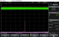
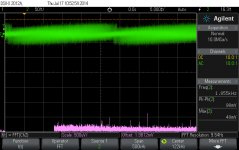
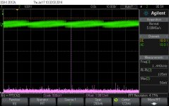
I took today some FFTs of this noise.
There are here the most representative of these snapshots. It can be seen on pic 10 a very stable pick, which is in fact some "residuals" of the clocking signal (108Mhz) for ES9018 in my system... BTW, the clock frequency have nothing to do with the shape of the noise. There is exactly the same shape and the other of the noise particularities at lower clock frequency for the Sabre chip...
Please note that the measured noise amplitude level (Vpp) is around 100mV, while the FFT calculations are for 1mV/div range and under.
Attachments

Last edited:
I'm not sure how to interpret the spectrum shots? They seem to show different frequencies form a few kHz to 100's of kHz.
Is it not possible to show a complete spectrum from say 1kHz to 100kHz instead of these separate shots?
Jan
Is it not possible to show a complete spectrum from say 1kHz to 100kHz instead of these separate shots?
Jan
I have chosen to divide the spectre in small parts, because my scope have a particularity to show FFT calculations. It does not exactly as a spectrum analyser...
There are some more pics here...
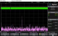
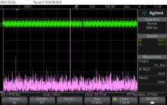
In pic A there is shown a 200Khz bandwidth, and the only frequency to be seen here is 121 - 122 Khz one from the analysed signal. So, I should go down in bandwidth (span) to view some another more details/picks...
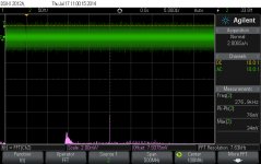
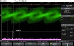
In pic B the centre of the spectre is 50Khz, and we can well see the 17,6Khz pick of 1mV of the 92 mVpp of the whole noise signal. Please note that it is not outputted any audio signal while we see these noises. The speakers are dead silent (when they are connected at the output). The outputted audio signal in the presence of this 1mV 17,6Khz (of that 90mV whole HF noise spectre), it is up to/ into 16Vpp... The sound of a trumpet at this full level (approx 10W power) of 16Vpp on output is just painful. The silence of a recording is as silent as no any audio signal on the output... Well, no just old recordings.😉🙂 There is not ever possible to hear this 1mV even with the ear right over the piezo tweeter..
Well, further to pic C... Lowering more the bandwidth of the spectre to 50Khz, I have the centre on 20Khz. So we have 0Hz to 2o Khz (centre), and 20Khz to 50 Khz (visible to 40Khz) the rest of the spectre in the right side of the display centre.
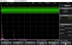
We can see here some more details. 17,6Khz and a quite high pick of 2,72Khz. I have measured these picks previously to save this picture. Therefore I marked it with quite precise figures.
And to conclude, a very interesting picture (D). I have lowered the intesity of the display. So we can see some more details of how the noise is shaped... There is in picture the same pick of 17,6Khz.
What you may mean/think?
There are some more pics here...
In pic A there is shown a 200Khz bandwidth, and the only frequency to be seen here is 121 - 122 Khz one from the analysed signal. So, I should go down in bandwidth (span) to view some another more details/picks...
In pic B the centre of the spectre is 50Khz, and we can well see the 17,6Khz pick of 1mV of the 92 mVpp of the whole noise signal. Please note that it is not outputted any audio signal while we see these noises. The speakers are dead silent (when they are connected at the output). The outputted audio signal in the presence of this 1mV 17,6Khz (of that 90mV whole HF noise spectre), it is up to/ into 16Vpp... The sound of a trumpet at this full level (approx 10W power) of 16Vpp on output is just painful. The silence of a recording is as silent as no any audio signal on the output... Well, no just old recordings.😉🙂 There is not ever possible to hear this 1mV even with the ear right over the piezo tweeter..
Well, further to pic C... Lowering more the bandwidth of the spectre to 50Khz, I have the centre on 20Khz. So we have 0Hz to 2o Khz (centre), and 20Khz to 50 Khz (visible to 40Khz) the rest of the spectre in the right side of the display centre.
We can see here some more details. 17,6Khz and a quite high pick of 2,72Khz. I have measured these picks previously to save this picture. Therefore I marked it with quite precise figures.
And to conclude, a very interesting picture (D). I have lowered the intesity of the display. So we can see some more details of how the noise is shaped... There is in picture the same pick of 17,6Khz.
What you may mean/think?
Attachments


Last edited:
Hi Coris,
... pls. allow me to jump back into this thread.
Your measurements look quite similar to the ones I made when developing the DAB - maybe you remember. The real thing is, that all these pics show modulated noise. I have a ES9018 evaluation kit too but did not yet work on it due to its unpleasant output configuration (I wanted to use tubes for the output driver).
Well, when developing the DAB, I found such modulated noise too from a PCM1798. At first - no idea where it came from, but I suspected artifacts from the internal clock as well as modulation from the time-slicing. Then I used better probes (250MHz) - and - the noise-band looked other. Anyway, the noise was still present!
I suspected now my 100MHz DSO to be responsible for the modulation and again I was right. Simply using another scope (an older 50MHz analog) showed no modulation at all. So I was sure, that there was noise present but all the modulation as well as the adjacent FFT figures my DSO showed were "digital fiction" only.
If you had a look at the article about the DAB, you will see that I used a ferrite pearl in the common GND-wire, which separates digGND from aGND. This approach cured the analog input from the inherent noise-band. I could not hear the noise from my truly efficient 102dB_SPL horn-speakers but on some occasions I suspected the noise to modulate again the treble (like the sound of cymbals). Anyway - inserting the ferrite pearl and these effects were gone.
Do you have an (maybe older) analog scope too? If yes, try it out!
Ciao, Barbara
Hi Barbara,
Thanks for your intervention, and specially, for advice. BTW, you may be very polite, but is not necessary to ask for permissions...
I do not use the evaluation board for ES9018, but a consumer product with it in. It may looks like the designers of this device did not placed this separation between the A/D GNDs. I used 300Mhz probe for these measurements, and unfortunately, I do not own an older scope... Also very interesting your experience with a older scope.
I just found out about some anomalies when to FFT some areas of the signal, with my digital device. So, a very modern digital thing it may not fit just well in some cases...
I do not try to find out where it come from this noise. There are so many digital stages inside the chip, that is normal to have such noises. What I wonder about is that this noises do not disturb at all the audio spectre. I mean the perceptual way to hear the sound of an audio signal. This is a little bit difficult to understand... Maybe it is not just by chance...
I could not detect any disturbances in high end of the spectre with all these noises at the level shown here. The highest notes of the sounds are reproduced with exceptional accuracy. The cymbal or bells or other high percussion notes of sounds just goes in into the head, feel like... I don`t know how to describe this, but is just as pure as in real. Very impressing, I may say. With the filtering in between I/V and final, or other kind of filters in signal path, I could not reach such purity of the sounds. But when I see the noises on output, then start the wanderings/confusions...
Actually this discussion about this noise was started from my experience published here with the caps over the output differential phases of the ES9018 DAC. I found out that these caps alter even more this noise, it change its shape, and it increase its level. The same trick it works very well for my DAC based on PCM1792 (also without any filtering in signal path). About this I was going to find out why, actually...
Hi Coris,
but anyway, I noticed this intermodulation in the highs - but maybe I only imagined - I cannot proof. I do not know any measurement method to verify. The only matter of truth that could be seen at the scope's screen was, that the beam-line was sharper resp. narrower after inserting the ferrite pearl. After this conversion I could not notice any of the side effects mentioned.
Maybe the other method of putting an RF-trap at the output could have helped too. I wrote this article many years ago, while today I would not call the "trap" a kind of filter but more an attenuator for RF into a likely capacitive acting load.
This noise reminded me on the noise-shaping of some digital musical instruments like dig. synths et al.
BTW - I forgot in my last quote to tell you what I heard from a DJ-friend: At a performance, noise from a "tuned" soundcard interacted (faithfully demodulated or resonated) with a powerful Class-D-amp the way, that the whole system went into overload while there was really nothing to hear from the speakers. The next day he found the tweeters were burnt. Anyway the "tuning" consisted mainly of bridging all antialiasing filters...
Inserting the "RF-trap" to the output cured the problem.
So, a very modern digital thing it may not fit just well in some cases...
Anyhow, even a DSO has its sampling rate, which can be the source of such fake measurements. Digital Fiction as I told you in my last quote.
Good luck and have a fine WE, Barbara
In my post 448 is to be seen a quite strange signal shape in the scope snapshots presented. I found out why it looks like this. There is my Agilent (now Keysight) scope which alter the original signal, and show it modulated in intensity.
Well, one should trust a measurement device, but not an Agilent one... At least not 100%...
There is the FFT function which alter the signal, and introduce such spurious...
Well, one should trust a measurement device, but not an Agilent one... At least not 100%...
There is the FFT function which alter the signal, and introduce such spurious...
Hi Coris,
... like I told you!
But - anyway, I am bit wondering about that you did not know about, that you NEVER can trust digital test equipment if it comes to chaotic signals -> like noise. 😉
Ciao, Barbara
... like I told you!
But - anyway, I am bit wondering about that you did not know about, that you NEVER can trust digital test equipment if it comes to chaotic signals -> like noise. 😉
Ciao, Barbara
Yes, you had right.
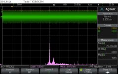
Actually this kind of noise the ES9018 output is not chaotic signal at all It is a well modulated "something"...
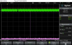
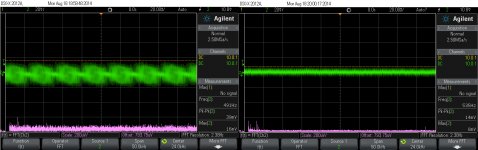
Please take a look at this snapshots here (sorry, I have to use further my digital Agilent...).
There is in pictures the outputted noise from the ES9018, and the same channel noise when the DAC is not active, but the system is powered. The FFT calculations shows no any specific frequency, even though is to be seen a clear modulated noise signal. Why is not reflected that modulation in FFT? Is something wrong with the scope and its FFT function? Or is really no any specific frequency there in that modulation? There is obviously that is a frequency which modulate the noise. But where is that (out of the FFT plot)?
The shape of the noise is similar in FFT, when ES9018 is active, to the noise in the system, when the DAC is not active (only the overall level is lower).
I think is quite interesting this similarity, but I do not know if it come from the scope or is in fact nothing there...
Please ignore the alteration of the intensity of the displayed signal, which it looks very well as a $ shape... This is for sure Agilent to be blamed for...
Actually this kind of noise the ES9018 output is not chaotic signal at all It is a well modulated "something"...
Please take a look at this snapshots here (sorry, I have to use further my digital Agilent...).
There is in pictures the outputted noise from the ES9018, and the same channel noise when the DAC is not active, but the system is powered. The FFT calculations shows no any specific frequency, even though is to be seen a clear modulated noise signal. Why is not reflected that modulation in FFT? Is something wrong with the scope and its FFT function? Or is really no any specific frequency there in that modulation? There is obviously that is a frequency which modulate the noise. But where is that (out of the FFT plot)?
The shape of the noise is similar in FFT, when ES9018 is active, to the noise in the system, when the DAC is not active (only the overall level is lower).
I think is quite interesting this similarity, but I do not know if it come from the scope or is in fact nothing there...
Please ignore the alteration of the intensity of the displayed signal, which it looks very well as a $ shape... This is for sure Agilent to be blamed for...
Attachments
hmmmm... a lame reminder? 😀Please ignore the alteration of the intensity of the displayed signal, which it looks very well as a $ shape... This is for sure Agilent to be blamed for...
Hi again Coris,
well I had to say one more time, you should not blame the Agilent DSO, since any other DSO will show such "digital fiction" too. The failure was to apply noise - a chaotic signal (better say statistically distributed signal across a given bandwidth) to digital equipment. All you can detect is dependent on its sampling frequency and the functioning of digitally controlled filters (-> FFT). Using better or even less top frequency probes will change your screenshot. So all you can see is a result by chance ...
Using an analog white noise generator (f.e. zener-noise-generator) as the source will give similar results.
Did you ever think about the sampling theory? Well, try this out -> simply digitally synthesize a sine wave of 20kHz using 44,1kHz sampling (like CD), burn to a disk and watch by any scope what's coming out of the player. No oversampling or time-slicing will help to recover this poorly noodling wave! You can see it drastically from app. 5kHz (two octaves below) on ...
Now imagine what happens if you sample a statistically distributed noise band!
You should not blame YOUR DSO, as this is an inherent fault of any digitally sampling device by itself. A system fault so to say ...
Ciao, Barbara
Once more,
sorry I forgot to comment to your screenshots:
The first one simply shows more amplitude than the second one. That could be due to some muting facility in your player (don't really know, as I do not know the exact schematic).
But there is something interesting at the FFT-traces too: It shows maximum content of harmonics at the start of the trace (the lowest frequency). That has to do with the transient effect of any digitally controlled filter. Therefore techs always set the low frequency corner at least for one octave lower than was to be tested. A well-known effect!
When testing 20Hz to 20kHz you had to set the corners at least to 10Hz and to 100kHz as there are strange artifacts at the upper corner too.
You should never trust any digitally created FFT for the lowest and the highest octave. But normally it is worse at the top of the range ...
Ciao, Barbara
I'm reviving this discussion because of a few experiments I've recently run, providing perhaps some small insight into the "Rasmussen Effect" filtering.
I built a DAC using the Buffalo IIIse board and Lundahl LL1676 transformers on the output feeding the grid of a 26 DHT tube output stage - the LL1676s convert the balanced output of the DAC into SE, remove the DC offset from the DAC, flip the absolute phase of the signal to reverse the effect of the single DHT tube, and allow the -9V grid bias to be applied to the grid of the 26, which is directly connected to the LL1676. There is no ground connection on the primary of the LL1676, it is simply taking the voltage outputs of the DAC +/- and summing them.
I configured the snubber and primary resistance of the LL1676 to achieve exactly a 1.3dB rolloff at 20kHz vs 1kHz, and indeed this sounds very, very good, with great clarity and soundstage while not sounding rolled off. FYI, this means using a 3nF/1k snubber on the secondary and an addition 3k3 resistance on the LL1676 primary; the LL1676 is series connected on both primary and secondary in a 2:1 arrangement.
So, employing the Buffalo IIIse oversampling and FIR filter (OSF) with S/PDIF input from my CD/HD player, this sounds great! The interesting part came when I connected a Sonore USB/I2S board to the DAC...
The Sonore board has an optional OSF of its own which they claim uses a "sophisticated partial minimum phase filter that significantly reduces pre-ringing". I spent the better part of yesterday listening to HD computer files played through the Sonore USB board, with the Sonore OSF ON and the Buffalo OSF OFF and vice versa many times over. I found that using the more sophisticated Sonore filter with my DAC produced a very smooth sound, but it was too rolled off in the highs compared to the Buffalo OSF (with its FIR filter), which sounded better in the highs.
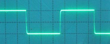
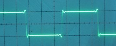
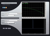
In an attempt to explain these very noticeable results to myself, I did a little digging on FIR filters and their effect and found the following on the TotalDAC website, which I thought was interesting. Picture #1 shows the response of a DAC without correction for HF rolloff versus corrected for HF rolloff using an FIR. Without the FIR, the response is rolled off by about 3dB at 20kHz, and with the FIR the response is flat up to 20kHz. In the time domain, scope shot #1 (picture #2) shows the slightly rounded edge at the front of the square wave when no FIR is used, and scope shot #2 (picture #3) shows the response using an FIR filter (for illustration purposes the amount of ringing is not important, just the fact that the FIR induces ringing is the point). It is clear that picture #3 shows significant ringing of the square wave, so the price to pay for restoring the frequency response to flat using an FIR filter is ringing on the leading edge of square waves (this may be obvious to the digital gurus here, but it was new knowledge to me); I expect that in some FIR implementations the ringing may be substantially more than in picture #3. In my experience with building and testing analog audio gear, excessive square wave ringing leads to the familiar HF glare sometimes heard with digital - the fact that the simple Rasmussen filter reduces glare while not excessively rolling off the highs seems to point to the mechanism being a reduction of the FIR-induced ringing effects while not excessively removing the positive effect of FIR filters on the frequency response. This is supported by my good experience using the 1.3dB rolloff on the output of the Buffalo employing FIR filtering.
Now, what gets interesting is what happened when I used the same 1.3dB rolloff output circuit with the Sonore "sophisticated OSF which significantly reduces pre-ringing"...although smooth sounding the HF was definitely too rolled off sounding. It seems that reducing the ringing using both the partial minimum phase filter and the Rasmussen Effect filter results in too much HF loss...in my opinion this points to the Rasmussen effect as being one of reduction of ringing effects due to FIR without losing too much of the positive effects of FIR in frequency response; in other words a tradeoff between the time-domain and frequency domain responses.
Now perhaps I could just go with the Sonore filter and remove the Rassmussen Effect filter to get a technically "better" result, but I use my DAC with both the USB input and the S/PDIF input, and the Sonore filter only functions on the USB input (because it's on the separate USB board), so my S/PDIF listening would then not have the benefits of the Rasmussen Filter, so my choice is to leave the Rasmussen filter as-is and only use the FIR filter on the Buffalo board to process both USB and S/PDIF inputs. Perhaps if I someday move completely away from S/PDIF I can revisit the Sonore OSF/Rasmussen Effect removal.
The above is not a technical treatise by any means, but anecdotal evidence that I hope may shed some light on this discussion. Constructive comment/discussion is the goal.
PS: the FR plot and scope shots were taken as illustrations from this website:
TOTALDAC, principles
I built a DAC using the Buffalo IIIse board and Lundahl LL1676 transformers on the output feeding the grid of a 26 DHT tube output stage - the LL1676s convert the balanced output of the DAC into SE, remove the DC offset from the DAC, flip the absolute phase of the signal to reverse the effect of the single DHT tube, and allow the -9V grid bias to be applied to the grid of the 26, which is directly connected to the LL1676. There is no ground connection on the primary of the LL1676, it is simply taking the voltage outputs of the DAC +/- and summing them.
I configured the snubber and primary resistance of the LL1676 to achieve exactly a 1.3dB rolloff at 20kHz vs 1kHz, and indeed this sounds very, very good, with great clarity and soundstage while not sounding rolled off. FYI, this means using a 3nF/1k snubber on the secondary and an addition 3k3 resistance on the LL1676 primary; the LL1676 is series connected on both primary and secondary in a 2:1 arrangement.
So, employing the Buffalo IIIse oversampling and FIR filter (OSF) with S/PDIF input from my CD/HD player, this sounds great! The interesting part came when I connected a Sonore USB/I2S board to the DAC...
The Sonore board has an optional OSF of its own which they claim uses a "sophisticated partial minimum phase filter that significantly reduces pre-ringing". I spent the better part of yesterday listening to HD computer files played through the Sonore USB board, with the Sonore OSF ON and the Buffalo OSF OFF and vice versa many times over. I found that using the more sophisticated Sonore filter with my DAC produced a very smooth sound, but it was too rolled off in the highs compared to the Buffalo OSF (with its FIR filter), which sounded better in the highs.
In an attempt to explain these very noticeable results to myself, I did a little digging on FIR filters and their effect and found the following on the TotalDAC website, which I thought was interesting. Picture #1 shows the response of a DAC without correction for HF rolloff versus corrected for HF rolloff using an FIR. Without the FIR, the response is rolled off by about 3dB at 20kHz, and with the FIR the response is flat up to 20kHz. In the time domain, scope shot #1 (picture #2) shows the slightly rounded edge at the front of the square wave when no FIR is used, and scope shot #2 (picture #3) shows the response using an FIR filter (for illustration purposes the amount of ringing is not important, just the fact that the FIR induces ringing is the point). It is clear that picture #3 shows significant ringing of the square wave, so the price to pay for restoring the frequency response to flat using an FIR filter is ringing on the leading edge of square waves (this may be obvious to the digital gurus here, but it was new knowledge to me); I expect that in some FIR implementations the ringing may be substantially more than in picture #3. In my experience with building and testing analog audio gear, excessive square wave ringing leads to the familiar HF glare sometimes heard with digital - the fact that the simple Rasmussen filter reduces glare while not excessively rolling off the highs seems to point to the mechanism being a reduction of the FIR-induced ringing effects while not excessively removing the positive effect of FIR filters on the frequency response. This is supported by my good experience using the 1.3dB rolloff on the output of the Buffalo employing FIR filtering.
Now, what gets interesting is what happened when I used the same 1.3dB rolloff output circuit with the Sonore "sophisticated OSF which significantly reduces pre-ringing"...although smooth sounding the HF was definitely too rolled off sounding. It seems that reducing the ringing using both the partial minimum phase filter and the Rasmussen Effect filter results in too much HF loss...in my opinion this points to the Rasmussen effect as being one of reduction of ringing effects due to FIR without losing too much of the positive effects of FIR in frequency response; in other words a tradeoff between the time-domain and frequency domain responses.
Now perhaps I could just go with the Sonore filter and remove the Rassmussen Effect filter to get a technically "better" result, but I use my DAC with both the USB input and the S/PDIF input, and the Sonore filter only functions on the USB input (because it's on the separate USB board), so my S/PDIF listening would then not have the benefits of the Rasmussen Filter, so my choice is to leave the Rasmussen filter as-is and only use the FIR filter on the Buffalo board to process both USB and S/PDIF inputs. Perhaps if I someday move completely away from S/PDIF I can revisit the Sonore OSF/Rasmussen Effect removal.
The above is not a technical treatise by any means, but anecdotal evidence that I hope may shed some light on this discussion. Constructive comment/discussion is the goal.
PS: the FR plot and scope shots were taken as illustrations from this website:
TOTALDAC, principles
Attachments
Last edited:
Hi Magz
Thanks for sharing about your Sabre output using a transformer and filter. Nice work. I think your pragmatic approach trying different filter set ups empirically and noting the sound is the best but theory can guide you where to experiment.
The filtering theory is complex. The total DAC is using a FIR as a high band equaliser to be able to correct the R2R NOS topology -3dB roll off. It could be dangerous extrapolating that example to your Sabre that intrinsically must upsample to do the sigma-delta noise shaping . However you can get similar pragmatic results using a computer audio player like Foobar etc with equaliser capability to boost the high bands while still using and enjoying the Sonore minimal ringing filter and leaving your analogue filter in place for the CD as source.
The Sonore filter may well look like other filters that favour impulse response to the detriment of passband meaning high f roll-off:
Attachments
- Status
- Not open for further replies.
- Home
- Member Areas
- The Lounge
- DAC Filtering - the "Rasmussen Effect"