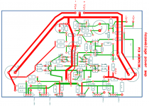
I am building this amp p2p so I need it to work at first start. In order to avoid possible stability issues I decided to postpone the 2 pole idea.
Here you can see 1st draft of the layout.
Comments are more than welcome as usual 🙂
Please note that for ease of layout I left the drivers and the output devices all related to the same heatsink..... would this be a major mistake ?
Here you can see 1st draft of the layout.
Comments are more than welcome as usual 🙂
Please note that for ease of layout I left the drivers and the output devices all related to the same heatsink..... would this be a major mistake ?
Attachments
Member
Joined 2009
Paid Member
PS: Would it be a terminal error to use the same heatsink for the output transistors and the drivers ?
You already know it's a bad idea 🙂
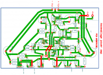
Now with thicker lines.
PS: Would it be a terminal error to use the same heatsink for the output transistors and the drivers ?
Why bring the output ground all the way over the board? The + and - lines can still be thicker (just remove less 🙂)
Now with thicker lines.
PS: Would it be a terminal error to use the same heatsink for the output transistors and the drivers ?
Give that 22u capacitor it's own ground wire (to the star point)
Now with thicker lines.
PS: Would it be a terminal error to use the same heatsink for the output transistors and the drivers ?
Move the + and - connectors to near the buffer capacitors.
You already know it's a bad idea 🙂
Just can not imagine how to add an extra heatsink to this rig.
Maybe it will work with a common heatsink
Member
Joined 2009
Paid Member
Just can not imagine how to add an extra heatsink to this rig.
Maybe it will work with a common heatsink
I guess if you have the Vbe multiplier monitoring the drivers temperature then it should work with a common heatsink. In my TGM8 I didn't need a heatsink on the drivers (due to design of the OPS) so I didn't face that problem and hence don't have direct experience to share.

I'm not sure I have it all connected as intended, but it serves the purpose. This shows how each (and every) ground point is separately connected to the central star point. The layout can be improved a bit by rotating the reservoir capacitors.
Attachments
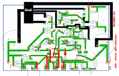
My 2 cents - make the traces, connected to the output transistors' collectors and emitters, emitter resistors, output of the amplifier, ground and rails (close to the output stage), as "fat" as possible (and as short as possible) - these are the traces, where the high currents will pass-through to the output load.
Cheers,
Valery
Cheers,
Valery
My 2 cents - make the traces, connected to the output transistors' collectors and emitters, emitter resistors, output of the amplifier, ground and rails (close to the output stage), as "fat" as possible (and as short as possible) - these are the traces, where the high currents will pass-through to the output load.
Cheers,
Valery
Yes, that to 🙂
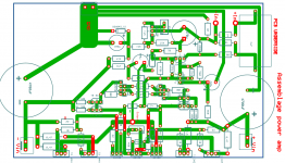
Here we go...
Thank you for your input Valery. I am going to do this p2p so I will use 0.8mm wire for the high current strips.
Or you could use 6mm2 for the high current parts.
https://www.flickr.com/photos/fransdewit/12678222314/in/photostream/player/
Member
Joined 2009
Paid Member
Use 'fat' bond pads on components that are physically large - especially the rail filter caps - the reason is that you don't want physical pressure on the large caps pushing the bond pads off the pcb substrate.
I like the "flying" rails.
Will also include 4amp fuses on the Vin rails.
Also need a notch filter in the output (coil // resistor).
Will also include 4amp fuses on the Vin rails.
Also need a notch filter in the output (coil // resistor).
- Home
- Amplifiers
- Solid State
- Assemblage Power Amp