Ahhhh 🙂 I did not see that, but (the original value) show as 1 milli ohm 🙂
Yeah, you would need an incredibly powerful source to drive that input 😛
Why not ?
Can you post a schematic ?
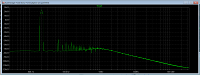
0,005641% THD 20K 100W 4ohm @50mA
values : https://sites.google.com/site/opampbasedamp/brute.csv

Thank you UX86.... good food for the mind.... I will study this and get back to it latter.
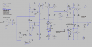
Now I am updating the Assemblage schematic using the 3 bjt input stage from Ingram.
As far as I can see, you've got gain = 1 here (100% GNFB) - in this case this kind of level of distortion is no surprise 😉
The reason is R7 = 1 mohm (0.001 ohm). It will not work this way in real life 🙁
Cheers,
Valery
Thank you so much Valery..... I too was not believing the graph but needed your eagle eyes to detect the issue.
Anyway this is growing steady.
Just implemented ingram's 3 bjt input and completely got rid of 2nd.... I am afraid this could sound somehow "clinical"
Attachments
Well, I am now learning how to use spice so maybe it is my fault.
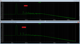
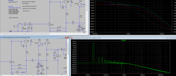
Here you have THD for both versions.
I would really appreciate your comments..... single pole has 2nd apparent but it seems to me that overall THD is lower with two pole.
Here you have THD for both versions.
I would really appreciate your comments..... single pole has 2nd apparent but it seems to me that overall THD is lower with two pole.
Attachments
Last edited:
Well, I am now learning how to use spice so maybe it is my fault.
Here you have THD for both versions.
I would really appreciate your comments..... single pole has 2nd apparent but it seems to me that overall THD is lower with two pole.
In my opinion you should continue with the original design, later it may be a good experiment to build this alternative design. The difference is not very big (in simulation) and after building the 2-input-transistor version you will always want to know how the 1-input-transistor version sounds.
In my opinion you should continue with the original design, later it may be a good experiment to build this alternative design. The difference is not very big (in simulation) and after building the 2-input-transistor version you will always want to know how the 1-input-transistor version sounds.
I sense some negative thoughts about this second option..... Did you have time to do some sim experimentations ?
I sense some negative thoughts about this second option..... Did you have time to do some sim experimentations ?
No nothing negative, but the performance (in sim) is comparable, and you started with the 1-transistor version, and I think that it is always best to finish what you start 🙂
Then afterward the 2-transistor version can be done and there is something to compare.
Alternatively, switch to the 2-transistor version and what tomorrow, switch to the ... version and then ...
I do not see a compelling reason to switch now, unless we would agree that the amp at hand will be totally crap, and that we are going learn nothing.
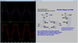
MosFet Clipper II
A Mosfet pair like these seems to be a possible choice 🙂
http://www.onsemi.com/pub_link/Collateral/NTUD3169CZ-D.PDF
A Mosfet pair like these seems to be a possible choice 🙂
http://www.onsemi.com/pub_link/Collateral/NTUD3169CZ-D.PDF
No nothing negative, but the performance (in sim) is comparable, and you started with the 1-transistor version, and I think that it is always best to finish what you start 🙂
I do not see a compelling reason to switch now, unless we would agree that the amp at hand will be totally crap, and that we are going learn nothing.
Ok, that settles it then. I also am not totally at ease with the two pole idea and as I am building this amp for learning purposes I will firstly stick to the single pole.
It sims incredibly stable and the lower the miller cap (C1) the lower the high freq distortion. (Naturally because with a lower miller cap, there is more high freq amplification and so more feedback with consequent lower distortion).
I simulated three different miller cap values (22p 48p 100p) and am not sure but all seem quite stable.
I kept C2 (phase lead compensation cap) fixed at 22p because it is an easy value to get.
Attachments
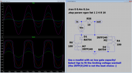
And a minimum component count version (making usage of the MosFet's body diode, but now you must use complementary MosFet's (with equal Vgs values)).
Now the mosfet clipper is really important.
Where should I place it ? Does it create any "bad" influence in the input ?
Now the mosfet clipper is really important.
Where should I place it ? Does it create any "bad" influence in the input ?
At the input, where the diodes where. Try it (in sym) and see what the effect are (while not clipping, and while clipping (you can do that 🙂))
At the input, where the diodes where. Try it (in sym) and see what the effect are (while not clipping, and while clipping (you can do that 🙂))
Probably it is better to use the one with the 'extra' diodes, you can then use 2 N (or P) channel mosfets and matching Vgs and Rdson wil be easier.
Member
Joined 2009
Paid Member
RC, this is coming along very nicely. Some good thinking and sound decisions.
In my case I did see in my simulations quite a bit of benefit from the 3-device input stage. I'm not sure why you are not seeing it, but I suggest you play around it with it in your sims a bit more. Not suggesting you go back to this more complex approach but it might be nice to understand it further.
Why do you need the clipper again ? - the pcb layout and interpreting the sound/performance will be easier with the simplest circuit. Simulations make it too easy to add parts 🙂
Last edited:
Again, simulation does not show any distortion when I use this clipper at the input.
I am not sure how to set the limiting voltage. (As is it hard clips at 2.2v)
Also BAT54 is a schottky diode... why does it appear as a zener in LTSpice ?
I am not sure how to set the limiting voltage. (As is it hard clips at 2.2v)
Also BAT54 is a schottky diode... why does it appear as a zener in LTSpice ?
Again, simulation does not show any distortion when I use this clipper at the input.
I am not sure how to set the limiting voltage. (As is it hard clips at 2.2v)
Also BAT54 is a schottky diode... why does it appear as a zener in LTSpice ?
The limiting voltage is set by selection a mosfet with the Vgs specification equal to the clipping value (the IRF240 has a Vgs of about 4V).
- Home
- Amplifiers
- Solid State
- Assemblage Power Amp