Member
Joined 2009
Paid Member
Remember, the Simple P3a that inspired my TGM8 (which has only a single output pair) sounds very good despite the wingspread diagram. It does not use emitter degen resistors on the driver devices (your R1 and R2).
Two pole comp - if you haven't cut the boards already you could include space for it. Build the single pole first but still have the option later to convert to two pole if/when you feel like it?
Two pole comp - if you haven't cut the boards already you could include space for it. Build the single pole first but still have the option later to convert to two pole if/when you feel like it?
Last edited:
Yes, blue, that represents 2,65 volts in the bias spreader. The important is keeping the output stage from leaving that spot when the temperature change, temperature stability is very important.
Bigun, can I see your output stage?
I would recommend Transient Miller Compensation instead of the 2 pole comp.
I would recommend Transient Miller Compensation instead of the 2 pole comp.
I tried TMC on the Nobrainer that Recardo build before and it worked.
It seems to restrict the bandwidth a bit though, at least in my implementation but distortion goes down.
It seems to restrict the bandwidth a bit though, at least in my implementation but distortion goes down.
Member
Joined 2009
Paid Member
Bigun, can I see your output stage?
I would recommend Transient Miller Compensation instead of the 2 pole comp.
sorry, i dont know how to paste a link whilst doing this on an ipad - just do a search for my thread on "TGM8" on this forum, the output stage is shown in post 9.
How would you apply TMC to it instead of TPC ?
Last edited:
adding those 2 resistors makes the gain lower.
Yes that's the idea.
R1 R9 R2 R10 must not be considered if we use emitter resistors.adding those 2 resistors makes the gain lower.
Can you sim it again without those ?
R1 R9 R2 R10 must not be considered if we use emitter resistors.
Can you sim it again without those ?
Attachments
🙂 very good results Frans , can I see the output stage?
No 🙂 I'm sorry but no, this thing is going to be my future (I hope) and will (not at this moment) be published. The first version that will be marketed is almost ready. There has been 2.5 years of prototyping and auditions to reach this state, many more prototype's and enhancements will follow in years to come. Currently the amplifier has a 'natural' THD (that is all feedback, except local on devices, removed) of less than -50dB, I want to improve this to -80dB (in years to come). But hey... I will stay here and comment and contribute in this (and other) threads. First half of the solution is to know that it can be done 🙂
No problem Frans, I understand. Hope the best for your project.
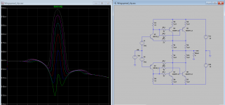
The more linear output stage without error correction or feedback that I know is the parallel of a large number of power transistors in a emitter follower configuration like this image, the best bias is at 56mA per device or 0.39A total.
The more linear output stage without error correction or feedback that I know is the parallel of a large number of power transistors in a emitter follower configuration like this image, the best bias is at 56mA per device or 0.39A total.
Attachments
- Home
- Amplifiers
- Solid State
- Assemblage Power Amp