I mentioned paralleling before as a means of distortion reduction.
You did it more massive though like in some american amps.
What about the JBL triple ?
Some think it is not that stable.
You did it more massive though like in some american amps.
What about the JBL triple ?
Some think it is not that stable.
Must learn how to sim this wingspread....
I belive it is better now, could you sim again using different emitter resistor values ?
0.22 0.33 0.47 0.8 1ohm ?
I mentioned paralleling before as a means of distortion reduction.
You did it more massive though like in some american amps.
What about the JBL triple ?
Some think it is not that stable.
Normally big amplifiers sound better, and there is a technical explanation for that, paralleling power transistors gives lower output impedance less distortion and a more robust amplifier.
I don't know JBL triple, is the same of Locanthi T circuit ? If yes, then you right, adding the prédriver transistor makes the circuit less stable, but that is easily fix by using some capacitors and base resistors.
The Bryston , I never heard, do you know any circuit that has values in the resistors?
Yes, the Locanthi T.
I think it is used by Aire without overall NFB and the distortion is ok ( 0.1% ? ).
Somewhere i found a complete Bryston circuit. I have to search.
I think it is used by Aire without overall NFB and the distortion is ok ( 0.1% ? ).
Somewhere i found a complete Bryston circuit. I have to search.
Must learn how to sim this wingspread....
I belive it is better now, could you sim again using different emitter resistor values ?
0.22 0.33 0.47 0.8 1ohm ?
You can download the example circuit from Bob cordell site in figure 19.4
CordellAudio.com - Tutorial Simulations
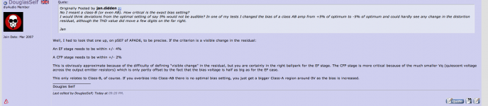
In my personal opinion the great feature of CFP output stage is the good thermal stability, but to have that, you have to use a circuit like Bigun uses.
Adding emitter resistors makes the crossover distortion worse.
No problem Frans, I understand. Hope the best for your project.
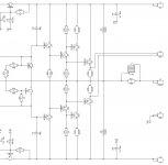
The more linear output stage without error correction or feedback that I know is the parallel of a large number of power transistors in a emitter follower configuration like this image, the best bias is at 56mA per device or 0.39A total.
Doesn't that look good 🙂 now with halve the number of devices. I dream of these things.
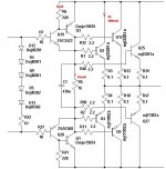
Here is the Bryston.
Q5, Q6 can also be MosFets.
I used this kind of topology in a number of designs with Sanken transistors (2SC2922/A1216) - like it a lot!
Low distortion, solid-sounding...
Attached is a fragment of my design with the values. I used it with +/- 52V rails.
Cheers,
Valery
Attachments
Last edited:
Have to take a better look at the bryston.
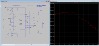
just for curiosity this is the wing from the output error correction amplifier that I will publish in diyaudio this week. It will use error correction and TMC.
That looks great, be sure that I will read your article with great attention.
That looks great, be sure that I will read your article with great attention.
Damir have start a new thread with a amplifier that uses my error correction circuit.
http://www.diyaudio.com/forums/solid-state/260308-gainwire-ngnfb-classb-poweramp.html
Damir have start a new thread with a amplifier that uses my error correction circuit.
http://www.diyaudio.com/forums/solid-state/260308-gainwire-ngnfb-classb-poweramp.html
And follow that thread 🙂
Valery, is that really a*2mH coil ?
I asume it is a 2uH.
You're right, it'a typo of course 🙂
In my personal opinion the great feature of CFP output stage is the good thermal stability, but to have that, you have to use a circuit like Bigun uses.
Adding emitter resistors makes the crossover distortion worse.
So you mean I should use only collector resistors (to output) instead of emitter resistors ?
- Home
- Amplifiers
- Solid State
- Assemblage Power Amp