LOL.
Who says TDA2050 is bad? 🙂 It's excellent too. And Low cost. 🙂 They are like Mini-GainClones as referred to by some audio gurus. As I said many times, my earlier active 3 way TDA2050 system can easily outperform many commercial systems. And I love their quality. Trust me, they are super cool too when used wisely.
And we, the DIYers, are always in search of the next dream amp. 🙂
All the best.
i am not in for 3 way complicated system just a 6 channel amp powered by 2050 and two subs powered by 7293. your project is overtly ambitious but i know at the end of the day, if i end up with a capable 6.2 amp i can atleast mould the parts it to better amplifiers like you without rewasting money on transformers chips etc etc again.
i am not in for 3 way complicated system just a 6 channel amp powered by 2050 and two subs powered by 7293. your project is overtly ambitious but i know at the end of the day, if i end up with a capable 6.2 amp i can atleast mould the parts it to better amplifiers like you without rewasting money on transformers chips etc etc again.
TDA2050 is a powerful chip. I am sure you will get awesome thundering sound with superb clarity when you will use them in tandem altogether.
Also you are blessed as you have great speakers in your possession. 🙂
So all the best and happy safe-building.
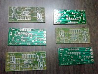
Second attempt with a new PCB 🙂
This time with the recommended 16V zener .
Great design, great sound. 🙂
This time with the recommended 16V zener .
Great design, great sound. 🙂
Attachments
Last edited:
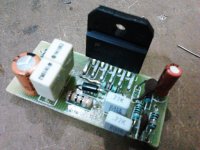
Second attempt with a new PCB 🙂
This time with the recommended 16V zener .
Great design, great sound. 🙂
Nice work
Nothing sir. 🙂 The zener and a resistor are hidden behind the 1uF caps.Very low component count.
What have you missed out?
The amp is in operation since last 4 hours or so.
Thank you sir! Credit goes to you. 🙂Nice work
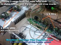
That heatsink is for sure fine for two chips. If you only have one sink I would attempt three chips.
............................
You are right sir !!
Added two chips. All fine. 🙂) Will add another one and test.
Thank you. 🙂
Attachments
I've just finished a PSU designed by sir Mile for the ML3 preamp/equalizer section. It's working great.
I was wondering if a similar PSU can be made for 6 X LM3886 chips or is that just redundant/overkill here?
If the answer is yes, which PSU Circuit of Sir Mile should I make?
I was wondering if a similar PSU can be made for 6 X LM3886 chips or is that just redundant/overkill here?
If the answer is yes, which PSU Circuit of Sir Mile should I make?
I'm not sure but I am sure that you dont need much of a complex supply for LM3886. I use an unregulated psu. Just a transformer followed by a rectifier followed by 40000uf then about a small amount of resistance followed by another 20000uf. Its basically the psu at the end of the F5 manual. Works and sounds great.
I'm not sure but I am sure that you dont need much of a complex supply for LM3886. I use an unregulated psu. Just a transformer followed by a rectifier followed by 40000uf then about a small amount of resistance followed by another 20000uf. Its basically the psu at the end of the F5 manual. Works and sounds great.
Thank you sir.
Could you kindly post a diagram along with the value and wattage of the Resistor of your supply?
Wow! You are fast! Great anticipation of the next question!!
The moment I finished posting the earlier question, I found you had already given the answer! Much Appreciated!!!
3W .47R
Look at last page of the linked pdf
Thank you sir. 🙂
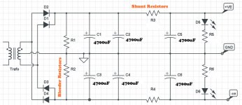
Here is my LM3886 PSU plan. Is it correct ?
Attachments
Last edited:
1)How about using snubberized power supply system by carlos filipe?
2) Will using a big(>10000uF) smoothing filter affect the response(Eg:frequency response) of the amp in any negative way? or is it 'the bigger the better'?
3)@CSOM: Can you please post the values of R5 & R6?
If it is going to help anybody,power supply guide:http://www.decdun.me.uk/gainclone_psu.html
Last edited:
Prashanth, I use a 1.5k or 1.8k resistor for R5 and R6 in series with the LEDs. I calculate the values using ElectroDroid app of Android Phone.
I found a problem with my one of my LM3886 amps.
The 10 Ohm 1/2 watt resistor in the Zobel Network in one channel is getting burnt whenever the AMP is clipping. And smoke comes out of that resistor whenever that happens.
The other channel is okay though.
But the sound of both the channels is normal .
Any solution please ? 🙁
The 10 Ohm 1/2 watt resistor in the Zobel Network in one channel is getting burnt whenever the AMP is clipping. And smoke comes out of that resistor whenever that happens.
The other channel is okay though.
But the sound of both the channels is normal .
Any solution please ? 🙁
Last edited:
- Home
- Amplifiers
- Chip Amps
- LM3886 Schematics + PCB