Good Andrew T... seems you are rigth...my own fuses
the ones i use are made by myself and they are not precise...so, your suggestion is very good and i agree that people should use higher rating fuse to the application.
The wire i use melts in 2.6 amperes DC...but even the solder melted around the wire can change this..also the solder in big quantity are dissipating, sinking heat, cooling the fuse and this may increase the ampere ratio...seems my fuse can be 3 amps or even more in the reality...so..what you say makes sense and also come from correct calculation.
So your suggestion is 3.5A to rails and 7 amperes in series with the output.
Thank you,
regards,
Carlos
Attachments
Last edited:
question about psu for mk2 supercharge...
hello Sir Dx,
is it possible for the mk2 supercharge to have a supply voltage of around +/-68volts dc? because i tried it with the prototype i have with the following
resistor values: R16=1k, R19=2.2k,trimpot=680R resistor series with R20=150R,
reading from multi meter, bias voltage from 100R/2watts resistor is around 4.9 volts, but the dc offset is around 115milivolts measured from common ground to the out put of the amplifier.
i test the sound of the music, it is very clear and no hum or noise when the amp is on.
is the problem with my dc off set are coming from the high voltage from the rail with +/-68voltsdc?
regards,
marjohn
No Marjoh, there's no problem
Of course you have replaced all electrolitic condensers by higher voltage units...also the quantity of output pairs should be increased..also heatsink size, supply condensers, some resistance watts ratio and bootstrapp resistances value should be increased also...a small increase...use arithmetics, or linear calculations.
Bootstrap resistances are R14 and R15... you can add one to the other, increase the value using this base value and them decide if will replace one or two of them to match the value calculated.
If 4K7 is good for 55V, then XXX will be good for 68 volts...you know that x thing calculation.
4700.............55
X ................ 68
And them discover what is "x" and try the most near value you find in your part's box.
You should check if all transistors you're using can face 68V multiplied by two (136V) for safety reasons...as some of them faces rail to rail voltage swing (sligthly less than that)... also you should check maximum current in the SOA power transistor curves to decide how many transistors you will need..also you should check if your supply is good....it may have 68 but may have voltage drop to 55 or less when you drive your amplifier to power...if this happens, then you should not worry about your increasing in voltage..only condensers should be replaced, as you will have higher than normal voltage only in stand by mode..and no one listen music with volume at zero!
Be happy..post pictures from you, your amplifier, your dog, bicicle, surrounds, family, kids, cats, parrots, neighboors and all you have to share with us.
regards,
Carlos
Last edited:
thanks Sir Dx
Thank you Sir Dx, I will do the interpolation to calculate the values and im going to change the condensers to higher value if necessary, i will post the pictures later....
regards,
marjohn
Thank you Sir Dx, I will do the interpolation to calculate the values and im going to change the condensers to higher value if necessary, i will post the pictures later....
regards,
marjohn
You welcome Sir......here people have informations about how the amplifier works
Some friends have asked how the amplifier works ...
These were sincere in asking ... and several times I
had to send these links to them ... now made public
because I can just point out where the explanation is, in
thread .... I hope it is clear, reasonably precise and
correct in the theory, and that can be useful for you all...
So, please, take a look in these video (audio) files opening, in advance,
a good schematic image that may help you..better to produce a print that
will help you, as the video image is not that good:
YouTube - How Dx Blame amp works 1
YouTube - How Dx Blame amp works 2
YouTube - How Dx Blame amp works 3
YouTube - How Dx Blame amp works 4
YouTube - How Dx Blame amp works 5
YouTube - How Dx Blame amp works 6
YouTube - How Dx Blame amp works 7
YouTube - How Dx Blame amp works 8
YouTube - How Dx Blame amp works 9
And attached you have the schematic... then you will be able to follow.
Enjoy and be happy.
regards,
Carlos
Attachments
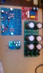
Blame ST power consumption to full power (100W/4 ohms) is 2.5A each rail..so..use, to each channel (separated supply, one to each channel) 12.500uf to 15000 to each rail..total of 30 thousand uf to each channel.
If you decide to use only 8 ohms...then you can divide by two these values.
Picture shows dual Dx supplies using 15k plus 15K each one of them.
regards,
Carlos
Carlos is there any particular reason you use 2 different capacitance values rather then just a single averaged size, so as an example say the amp above is using 2 x 2500 + 2 x 5000 for a total of 15000uf. Is there any reason why I couldn't use 4 x 3600-4000uf caps for a total of 14400-16000uf per rail?
buy 4 off 4700uF per channel.Carlos is there any particular reason you use 2 different capacitance values rather then just a single averaged size, so as an example say the amp above is using 2 x 2500 + 2 x 5000 for a total of 15000uf. Is there any reason why I couldn't use 4 x 3600-4000uf caps for a total of 14400-16000uf per rail?
You might get a discount for buying 8 for stereo. or buy 20 if the price suits you.
No my dear Luke...there's special reason.... was made that way just
not to have more much more capacitance than needed...to save money from builders, asking them only what is really needed.... this way, was avoided the use of two units of 10 thousand uf to each rail...but, of course and for sure you can use other combination of values, a couple of 15000uf will be good..also you can use higher capacitance if you want.
The use of 4 units was because the inductive filter in between these capacitors...you see that if we decide to use only two condensers to each supply, only two 15000uf units, then your inductor filter will not be in between the previous two condensers anymore....because no more two condensers to each rail.
You are free to change, the way you perceive as good for you..just keep four units, and arrange values in accordance your needs and availability of parts....just avoid to have less than 12500uf to each rail..doing that you will be rid of noises beeing reproduced in your speakers, together your music, while the amplifier will be working full undistorted power.... you can increase if you want....but avoid to exagerate..there are several very good designers that guarantees this blurred the audio.... despite i have not experienced that...i must say these guys that told me that know a lot more than me about audio electronics.
These guys i am talking about, are not only high level theorists...they are that kind of guys that knows a lot of theories but are always doing thing in the real world...... and these guys are the perfect ones...or, at least, the ones i respect the most.
The video link attached, shows you the need of huge condensers....video quality is not that good but may help to understand what i mean....also the rule i have learned and i have tested, it proved to be good and enough...5000uf to each ampere:
http://www.youtube.com/watch?v=KjE_ExOoWWs
Condensers, big electrolitic condernsers...the ones used for supply filtering purposes, when you put them to work and you measure them, you will notice that 5000uf in the rality are much bigger than that....maybe 7000uf.....also insulating voltge is just a guaranteed reference level...you can use it with a little bit higher voltage....these things usually have plus and minus 20 percent, because mains can have this voltage fluctuation too...analogic electronic is not that precise.
regards,
Carlos
Last edited:
I assumed this was the case that it didn't matter but figured I would ask the question while there was some discussion around the supply caps.
Thanks
Thanks
Don't ask the same question of Peter Daniel, unless you want to see the alternative view.
His philosophy results in a very different answer for smoothing caps.
His philosophy results in a very different answer for smoothing caps.
Quick question, can C10 in DX blame MKII be 47uF/63V instead 47uF/100V. I have couple in stock
No!...i am sorry, this one is the bootstrap condenser
and the voltage it will face is really big, it is not a good idea to use 63 volts condensers in that position.
This condenser has it's negative lead connected to the output line..and thi line swings from very high positive voltages to very high negative voltages (AC audio swing ) that are near the rail voltage...so..you may charge this condenser during the negative half cicle swing to more than 80 volts.... a 63 volts condenser may be damaged, leak or explode one day.
If you cannot find a 100 volts (or more) unit, them use two 100uf/63 volts connected in series.. you know...two doing the job one can do....this way you gonna be creating a 50uf by 126 volts condenser ..do it not to stop your amplifier construtions while you will be continuing to search by the correct value and insulating voltage.
regards,
Carlos
Attachments

Last edited:
Don't ask the same question of Peter Daniel, unless you want to see the alternative view.
His philosophy results in a very different answer for smoothing caps.
Yes, I always wonder about the size of the caps some guys use on chip amps, some of them seem to use rediculous amounts of capacitance, and I wonder how they aren't running into issues with inrush current not to mention circuits traces being able to handle the load. I'll admit to not knowing much about these thinigs though, only that I have seen mention of these issues in regards to having excessive capacitance and more then what a design can really handle.
I have my DX Blame boards up and running (in test mode, running from a +/-30V lab supply).
I have used standard transistors:
BC556/546
BD139/140
2SC2822/2SA1216
and Rudi's red boards
I initially built it as the ST version with C13 @ 82pF and noticed some hf fuzz on the positive going edges during overshoot into a capacitive load (2.2uF//10R). Changing C13 to 100pF makes no difference to this.
I then added C11 (18pF) and C25 (470pF), this tamed most of the oscillation, but not all.
C18 also helps slightly to reduce the fuzz.
C24 does nothing at all as far as I can see (obviously it's meant to slow the current source down, by for what purpose?).
Increasing the value of C23 changes the frequency of the oscillations (47n gives ~ 10MHz, adding 220n in parallel gives ~ 1MHz).
Anyone else had this problem? Any suggestions?
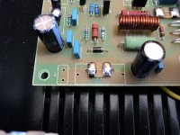
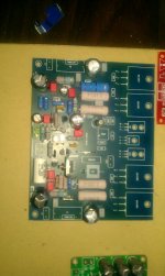
Progress so far
Here some pictures of progress so far. PSU, Speaker prot and softstart are also almost finished.
Forgot to buy the 2r2 resistors so still waiting on those. As soon as I receive them assembly can start!
Can't wait!
Here some pictures of progress so far. PSU, Speaker prot and softstart are also almost finished.
Forgot to buy the 2r2 resistors so still waiting on those. As soon as I receive them assembly can start!
Can't wait!
Attachments
- Status
- Not open for further replies.
- Home
- Amplifiers
- Solid State
- Dx Blame ST - Builder's thread - post pictures, reviews and comments here please.