I'd prefer a notch - I'd rather pull down the broad peak than boost the dip and potentially boost noise.
I just noticed that my FW410 crashed (@#$% M-audio drivers), which may explain why I can't get the emulator to work. I'll let you know if I get it running after I take care of a couple things before rebooting.
I just noticed that my FW410 crashed (@#$% M-audio drivers), which may explain why I can't get the emulator to work. I'll let you know if I get it running after I take care of a couple things before rebooting.
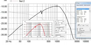
Now for the mid/bass. Luckily this is quite easy and if not for a peak in the response at 4400hz, the driver is reasonably well behaved. As we are crossing over low this can be ignored too.
One thing to note before I go any further is that due to the limited gate length the low frequency response of the mid/bass is severely limited. This has some impact on exactly how to fine tune the low pass. Having a near field splice to the far field response would help with this and is mandatory when designing a passive loudspeaker. With an active design it's easy enough to get around because you have complete freedom with setting the tweeter level and with setting how much baffle step compensation you want.
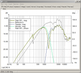
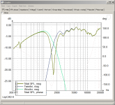
Either way due to the controlled nature of the mid/bass I've ended up with something that looks like this.

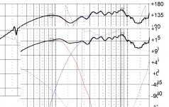
The next step is to combine them both and see how things then look.
The response is pretty dire, not so bad set one way, but the reverse null is terrible. I have also taken the liberty of setting the tweeter level.

If this were a passive loudspeaker we would now start to try little tricks and asymmetric slopes in an attempt at fixing the phase issues.
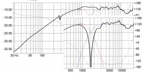
This isn't a passive loudspeaker though, so we should take full advantage of that fact and add in a time delay circuit. This allows us to keep our perfect LWR4 slopes.

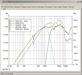
With the delay in place we now get a perfect symmetrical notch and a nice flat response on axis.
One thing to note before I go any further is that due to the limited gate length the low frequency response of the mid/bass is severely limited. This has some impact on exactly how to fine tune the low pass. Having a near field splice to the far field response would help with this and is mandatory when designing a passive loudspeaker. With an active design it's easy enough to get around because you have complete freedom with setting the tweeter level and with setting how much baffle step compensation you want.
Either way due to the controlled nature of the mid/bass I've ended up with something that looks like this.
The next step is to combine them both and see how things then look.
The response is pretty dire, not so bad set one way, but the reverse null is terrible. I have also taken the liberty of setting the tweeter level.
If this were a passive loudspeaker we would now start to try little tricks and asymmetric slopes in an attempt at fixing the phase issues.
This isn't a passive loudspeaker though, so we should take full advantage of that fact and add in a time delay circuit. This allows us to keep our perfect LWR4 slopes.
With the delay in place we now get a perfect symmetrical notch and a nice flat response on axis.
Attachments
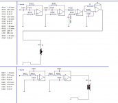
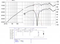
Finally here is the overall schematic.

Naturally you will have a baffle-step compensation circuit on the woofer and gain setting on the tweeter.
It bares mentioning however that we have just designed a speaker around a listening distance of 0.95 meters on tweeter axis. If this were a passive loudspeaker you'd want to set the mic distance to how far away you normally listen.
Also the mic is set in space on axis with the tweeter as the Dx and Dy parameters are both zero. You would want to set the mic position to your preferred listening height too. To do this you'd have to alter the Dy parameters of both the tweeter and mid/bass up or down by the same amount, to compensate for any difference in ear height. But do this after you've matched the initial measured combination to the predicted combination.
You can also measure the drivers to start with on the listening axis too.
As this is an active loudspeaker however these problems are less of an issue because of the delay circuit. You can position the microphone in your listening position and measure for the reverse null. If it's bad or off by a bit, you can tweak the delay circuit till the two drivers sum 'perfectly'.
Attachments
You have a point there Bob.. but as the overal level should remain the same, the only noise that can be pulled up by using a shelving filter is the noise in that op-amp/ filter stage.. on the same note, using a broad notch to flatten the hump lowers the overall level, which will then have to be pulled up again accordingly.. two sides of the same coin? 😕
5th, wat you are getting looks very similar to stuff I'm getting.. except that I get a relatively nice looking reverse-dip of about 10-12 dB or so..
Now, if I only let the optimizer run just long enough to get a reasonably flat FR, the reverse null is allmost non existent, but running the optimizer a bit longer, untill it starts to do only quite small iterations.. thats when I can get 10-12 dB null when reversing the tweeter. Not a terribly deep null though, but perhaps good enough??
Posting synch-problem! 🙂
Except for the notch filter, your schematic looks simmilar to mine and the values are not to far off either, so tha should mean I'm not that far off too.. 🙂
having said that, some of the resistor values in the HP section are a bit further out, meaning I have a bit moer of an "oddball" transferfunction, which in turn may explain that I'm actually able to get a reverse polarity null.
Regarding listening height, that depends wether I'm in the sofa, the armchair or just standing up! 🙂
As summation and phase varies with mick position, so will listening at different positions.. I guess I'll just stick to the tweter axis for consistency and simply adjust the height of the speakers if required. This is after all easy since the boxes are relatively small! 🙂
but back to delay.. is there a way to simulate this so I can evaluate what the benefit will be? Looks like you managed to do so?
I've allready worked out a good BSC correction based on earlier far-field measurements with good distance to surfaces (warehouse) and nearfield splicing, so the level at 1k is fairly representative of what's further down. As you assume, I allso have a levle setting for the tweeter, which I believe is indispensible.
Last edited:
As Bob mentioned it is preferable to use a notch if possible, this is also beneficial because it allows you to shape the response a little better around the xover point I'd imagine too.
Here is another version using a passive network for the notch filter, the series cap is necessary for the shunt notch filter to work, it also provide protection for the tweeter. My amps have protection relays in too and a sensitive DC detection circuit too, but I still feel better having the cap there.

Here is another version using a passive network for the notch filter, the series cap is necessary for the shunt notch filter to work, it also provide protection for the tweeter. My amps have protection relays in too and a sensitive DC detection circuit too, but I still feel better having the cap there.
Attachments
I look at it as you need to pad down the tweeter level anyway with the boost due to the waveguide. Attenuate near the end of the filter chain and you attenuate any noise upstream.
Boost the HF with a shelving filter and you boost HF signal along with ALL HF noise from previous stages.
BTW, the emulator works in the demo version.
Boost the HF with a shelving filter and you boost HF signal along with ALL HF noise from previous stages.
BTW, the emulator works in the demo version.
For the delay network you will have to build this yourself I think. LspCAD 5.25 comes with built in pre made filters, but comes with the limitation that you can't build anything other then what's pre built.
You can see the schematic for one in the pictures I've posted, in the last picture it's R1041, C1041 and the two R's. R doesn't have to be anything special, a value of 10k would work reasonably well, although you might prefer smaller to keep noise down. I've used 10k though and it's never been an audible problem.
One additional benefit to the delay circuit is its flexibility. It gives you the flexibility to easily try out different xover frequencies and slope types. If the delay wasn't there you'd have to constantly faff with asymmetrical stuff. All that's needed with the delay circuit is to simulated perfect acoustic targets, then set the delay till you get the required response with the polarity reversed.
It also means that you do not have to bother with configuring the simulation program for the phase. You get the acoustic targets how you want them, then you correct for the phase with your delay circuit by measuring the end product.
I look at it as you need to pad down the tweeter level anyway with the boost due to the waveguide. Attenuate near the end of the filter chain and you attenuate any noise upstream.
Boost the HF with a shelving filter and you boost HF signal along with ALL HF noise from previous stages.
BTW, the emulator works in the demo version.
This is very true Bob and in some of my active xovers I have placed a noisier stage directly before a low pass specifically so that it filters it out.
Good point Bob!
Fortunately for me, if I choose to continue down the shelving HF route, I actually have the shelving filter before the HP/LP section! 🙂
So you got the emulator to work??
I did look in to delay, or allpass filters a bit earlier in the thread, and what I found with the slopes I had then, was that I was seriously out of op-amps for the stages required for the necessary delay..
So I'm kind of fearing that even if I did perfect symetrical slopes, I would not be able to build the required delay-circuits...😱
I couldn't quite see from your plots 5th, how deep is that null you get?
I found that I could improve things quite a bit by juggling woofer level, optimalisation range and set level..
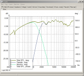
After tweaking this a bit, I got a HP transfer function that will have a 15 dB null according to the simulation.
To me, this looks quite good and I think I'll leave it at that and do the HF bit next..
Fortunately for me, if I choose to continue down the shelving HF route, I actually have the shelving filter before the HP/LP section! 🙂
So you got the emulator to work??
I did look in to delay, or allpass filters a bit earlier in the thread, and what I found with the slopes I had then, was that I was seriously out of op-amps for the stages required for the necessary delay..
So I'm kind of fearing that even if I did perfect symetrical slopes, I would not be able to build the required delay-circuits...😱
I couldn't quite see from your plots 5th, how deep is that null you get?
I found that I could improve things quite a bit by juggling woofer level, optimalisation range and set level..
After tweaking this a bit, I got a HP transfer function that will have a 15 dB null according to the simulation.
To me, this looks quite good and I think I'll leave it at that and do the HF bit next..
Attachments

Just added a bit of 12 dB oct HF shelving.. still a dip at 15K and a minor rise around 8k..
I guess I could still add some gain before the 20k peak becomes significant..
To get that 8K lift back in line, I could increase the woofer level a tad and optimize the HP to meet that, thereby leveling things out.
I guess I could still add some gain before the 20k peak becomes significant..
To get that 8K lift back in line, I could increase the woofer level a tad and optimize the HP to meet that, thereby leveling things out.
Attachments
Good point Bob!
Fortunately for me, if I choose to continue down the shelving HF route, I actually have the shelving filter before the HP/LP section! 🙂
Yes, except that there is no LP there to filter out the high frequency noise you'd hear as hiss, it's the tweeter network!.
I did look in to delay, or allpass filters a bit earlier in the thread, and what I found with the slopes I had then, was that I was seriously out of op-amps for the stages required for the necessary delay..
So I'm kind of fearing that even if I did perfect symetrical slopes, I would not be able to build the required delay-circuits...😱
Do remember that you should be able to use any leftover woofer parts on the PCB for the remaining delay stages. By the looks of things, for an optimal situation you'd need two delay stages each centred around 1.8khz.
I couldn't quite see from your plots 5th, how deep is that null you get?
-35dB.
I think you might be best off simming something you're quite happy with and actually building it and seeing how it measures/sounds. This would more then anything be to confirm that the simulation is matching up with the real world.
Also it would give you something to listen to, a bit of musical therapy might help alleviate any headaches you've acquired when staying stuck at the computer.
Headache.. well not there yet, but my eyes are starting to go a bit square...
Nothing I'd rather do than get the project together and start listening to music actually. The den's been like a electronics workshop and electro-acoustic lab for longer than I like to think about now...
As the last excercise of the evening, I tweaked the HF shelf and levels and added a 23k 24dB/oct LP which lobbed of that HF-peak quite nicely..
The resulting simulation shows a FR that stays more or less within +/-1,5 dB which would be quite good in real life.
The one thing I'm not entirely happy about, is the reverse tweter null, which is now only -10dB. Compared to your -35dB (!) that doesn't sound too impressive I guess.. and no more op-amps left to play with..
I think I shall reconsider a bit, see if a 2-stage delay will work and then see if a wide notch can tame the tweeter response...
But that won't happen today! 🙂
Attachments
Last edited:
Not that most can really hear much up there, but the rise is only 6 dB/octave. target 17K or so, 1st order and there will be less phase shift than a 4th order filter.
Hmmm.. one final observation I made..
In the general settings, I found that the measurement distance was set to infinite.. I changed this to 0.95 m, and Voila, a nice deep 20dB reverse polarity null! 😱 changed to 2m to check,and it was just as good there.
-20dB is of course not as good as -35dB, but I think it should be good enough, at least compared to other measurements & sims I've seen, e.g in Vance Dickasons loudspeaker cookbok.
Considering this, I think I'll have a go at implementing the filter set up I've hatched out so far..
Attachments
Bob,
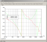
Looking at the phase plot for the drivers, it's obvious that it gets fairly steep above 10k. But do you think that is significant? Im just thinking that in this frequency range, to the extent we can hear stuff that high, the ear is only sensitive to magnitude changes, not time/ phase.
But anyway, do you think a 1st order filter will be "precise" enough? I'm sort of fearing that with a shallow filter, attenuation sufficient to kill the HF peak might dip down in to the slight 15k dip which is allready there??
Attachments
Just a bit of purism. I doubt we'd hear it, but then again considering that oversampled CD players sound better than the early ones with brick wall filters...
You have a point there.. there is some part of me cringing at all these filters! 😀
(but this is all probably just peanuts compared to what is going on with some passive filters and all the reactive stuff they throw at an unsuspecting power-amplieifer..)
I did a quick check with a 12dB oct filter, but then that 20k peak was suddenly more pronounced.. I think of the two, keeping that HF peak down is the lesser evil...
Anyway, orered up a bunch of odd-value resistors now, so I guess that in a couple of days we shall see how theoretical simulations fare when they meet real-life measurements!
Oh my.. *looking at the watch*.. I will be tired tomorrow, talk about getting carried away with stuff...
Finally,
Picked up the resistors for the new filter configurations I, or we, worked out on wednesday.
I have now modified the LP/HP sections, and measured the result!
I must say this looks very nice in deed.
The X-over region is very flat, and reversing the tweeter gives what I would describe as a fairly deep and clean notch!
And most important, it sounds very nice, obviously taking the HF droop in to account.
So far, so good, now it's time to add some shelving EQ to the tweeter..
Attachments

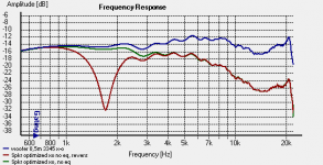
Now, the sheving HF eq has been added.
Now the high frequencies and details are present, allthough the sound is perhaps a tad bright. I need to re-adjust the tweeter channel gain stage a bit so I can reduce the tweeter level a dB or two.
The big surprise here is that the 20k response peak is absent.
This looks more like what I had expected with the 23k LP filter in place (not implemented yet)
This leaves me with two options; leave as is or increase the shelving a bit fill in more of that 15k dip and throw in that 23k LP if the 20k peak becomes too dominant again.
This is starting to look and sound like something!
Attachments
- Status
- Not open for further replies.
- Home
- Source & Line
- Analog Line Level
- Shelving 2nd order high-pass?