Wow.. this is crazy, looking at that software working to flatten the FR!!!
I wonder.. if I include that 12dB oct HF shelving filter in the schematic, if it will itterate that in conjunction with the XO to get an overall flat response??
I wonder.. if I include that 12dB oct HF shelving filter in the schematic, if it will itterate that in conjunction with the XO to get an overall flat response??
Oh my.. I can't believe it, it's doing it!!
I added the shelving filter to the circuit and i'ts working on it too, iterating everything!! This is just crazy!!
I added the shelving filter to the circuit and i'ts working on it too, iterating everything!! This is just crazy!!
It's giving me a very flat response up to just over 10k, but then there is that dip and HF peak again..
However, looking at what this software can do, I'm tempted to throw in some additional filter stage to see if it can use that to manage this problem for me.
Having said that, it is obvious that the software worked out a fairly asymetrical set of slopes to get a smooth transfer function. When I invert the tweeter in the schematic, the reverse-null is very non-symetrical.
Should I care about this?
If so, I could perhaps add some delay to alleviate this, but then I won't have any op-amp left for an additional filter stage to tame the HF peak..
No... hang on.. I re-started the optimizer again with the tweter reversed, and after getting a flat FR again, i reversed back to Normal, this time there was a very deep and fairly symetrical dip! 🙂
So that should leave room for a filter to kill the HF peak..
Last edited:
It's nice to see you figured out the teething problems. Yesterday, I too tried using your posted files from Holm and didn't have much luck.
Welcome to the world of computer simulation, it can be fantastic 😀
As you will have noticed, you can tell it to optimise around any number of components. The only trouble is the optimiser doesn't know what the individual components do. It simply alters a value and sees if your response moves closer to the target, if it does, it does it some more. To this end, it is usually better to do one thing at a time, ie let it try and get the response as good as it can with just your highpass. After that let it massage the notch filter into place etc.
Keep an eye on the component values and make sure it doesn't go off to an unrealistic extreme. Sometimes it needs to do this, and sometimes it just wrecks everything. For example, if you've got an electrical 4th order highpass at 2khz and you only need a 2nd order to reach your desired acoustic goal, it will try and set the f3 point of one filter block way out of band, say down to 200hz. Naturally to do this it needs to increase the resistor values, in this case you want to remove the unrequired filter. Other times it gets the idea that altering a certain value up or down is a good thing - which it isn't. Like trying to shape the roll off with the notch, when it should be done with the highpass section.
One other thing to mention is when you're optimising it is better to get the shape of the initial roll off, in the transition band, as accurate as possible, even if it means giving up some accuracy where the filter is say 15-20dB down. You can get the optimiser to do this by limiting the bandwidth of the optimisation process.
It's giving me a very flat response up to just over 10k, but then there is that dip and HF peak again..
SNIP
So that should leave room for a filter to kill the HF peak..
What you should be doing is optimising the transfer function of each driver individually, not both at once.
Get the acoustic roll off of the mid/bass to hit a perfect 1600hz 4th order LWR acoustic target.
Then get the tweeter roll off to hit a perfect 1600hz 4th order LWR acoustic target.
After having done this, if the phase is aligned there will be a massive null with the polarity reversed.
I have to stress what I am about to say next because it is very important, you CANNOT design the phase into the simulation at its current level, for that you need to do something else to 'calibrate' the system.
This can be a chore to do and is one reason why using the delay network is so nice, because you simply fiddle with it, measuring in real time time, till you get your reverse null.
Fantastic in deed! 🙂
This is like X-mas!
A very good point about being carefull about trying to do everything at once, I did notice some "strange" things happening here and there..😀
I obviously need to play around a bit so as to learn how to harness this tools by setting the right constraints.
I sure wish I had the full version that would allow me to save. Don't know what the full version would cost, put probably way too much to justify for some DIY'ing every now and then.
Anyway, now that I've figured out how to set things up, it's just a matter of setting up for a session with a clear aim of what to acheive.
My sincere thanks for introducing me to this very powerfull tool!!
This is where I get a bit stupid again..
I'm not following you entirely when you say I can't design the phase in to the simulation??
I believe there is an option for adding delay to the different drivers??
Well, I see tha this will not be the same as using an allpass filter, since these allso have a delay shifting with frequency.. but is it not possible to simply model the allpass filter in to the schematic??
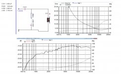
The DXT lens on the tweeter adds in a hump of gain that starts at around 12khz and then extends down to where you want to xover. What you want to do is remove this hump in some way, either through a passive filter or an active notch.
I have attached a passive filter that I use on mine. The component values aren't optimised as I cobbled something together out of the components I had lying around. It works however. My active crossover then changes that response into something useful.
How to calibrate the system for accurate phase simulation.
1) Place the microphone at a fixed known distance away from the loudspeaker cabinet, typically 1-2 meters and at tweeter height. Do NOT move the mic once it's in position.
2) Take a measurement of the tweeter.
3) Take a measurement of the mid/bass.
4) Take a measurement of both the tweeter and midbass playing together.
5) Measure the driver separation with a ruler, ie how far below the tweeter the mid/bass is and how far, if applicable, is it to the left or the right etc.
6) Go into LspCAD and load in your measured files.
7) In the driver setup thingy tell LspCAD how far below the tweeter the mid/bass is. In LspCAD 5.25, which I have, it has Dx, Dy and Dz parameters. Here you want to set the Dx and Dy of the mid/bass relative to the tweeter.
8) Somewhere there will be an option to set a general target response. Here you want to load in the file you created when measuring both drive units together.
9) Find where the program allows you to enter mic distance and set it to how far away your mic is/was when taking the measurements.
10) Remove any software filters present on the tweeter and the mid/bass, you want both of them unfiltered.
11) Now alter the Dz parameter on the tweeter (typically you move it backwards so -20mm or so), you can also alter the relative level of the tweeter up and down say by +-1dB if that helps. What you are aiming for is for the combined simulated response of the unfiltered tweeter and the mid/bass to match the actual combined measured response.
Once these two match (and if you've done it correctly they should match really well) you can then turn off the target response (point 8) and start simulating for phase alignment.
Doing all of that is a huge bother, but it has to be done if you want the predicted response to match up with the measured response. This is why using a delay circuit is so nice.
With perfect acoustic roll offs on both the tweeter and mid/bass you know they will sum really nicely if they are phase aligned. And to phase align them, all you need to do is tweak the delay circuit till you've got a deep null with the tweeter polarity reversed.
Attachments
Thanks a lot for the detailed advice, this will be usefull no end to keep me from going in circles and generally messing about too much!
That filter of yours seems to do the trick quite nicely. I'll see if I can get an active filter stage to do something similar perhaps. Since I'm doing axtive x-over in the first place, it would be nice to avoid any passive filters alltogether.
So far, I've taken the point between the tweeter and woofer as the on-axis position, but I'll change practice so as to be able to follow your guidelines.
another thing..when measuring the raw response of the tweeter, I must apply some highpass (in holmImpulse) to prevent damage from LF. Any advice on how low I can/ must go??
Tweeters are by nature a tiny loudspeaker in a sealed cabinet, so the excursion levels off below resonance. In other words (if the drive level is unaltered) as frequency decreases the excursion reaches a maximum point, but then doesn't go any higher. As long as you don't drive it too hard the tweeter will be fine. Just use your ears and keep the level comfortable.
I do recommend a series cap of some sort to protect the tweeter from any misbehaving electronics, or turn on/off thumps. You'd need something like a 50uf, if you want it to leave the tweeters response well enough alone. But if you're going to add in a protection cap anyway you could just as well use that cap as part of a passive filter that removes the hump.
With your active crossover, if it's a case of choosing between the notch filter or the delay network, I'd choose to keep the delay network every time.
I've been letting LSPCAD do its thing with my drivers for a couple hours now. Still optimizing, finally got the crossover near the target. I guess I gave it too many things to play with.
Things went much more quickly with Frequency Allocator, tweak and measure. LSPCAD would make it easier to design the analog equivalent of my digital filter, though.
Things went much more quickly with Frequency Allocator, tweak and measure. LSPCAD would make it easier to design the analog equivalent of my digital filter, though.
You can leave the microphone between the two drivers if you wish, it's not that important.
What is important is handling it in LspCAD in the right way. The way I described it before was making everything relative to the tweeter, so the Dx, Dy distances would be zero on the tweeter parameters. In other words the microphone is sitting on the tweeter axis. You can move the mic down 4cm if you wish and simply put that in to LspCAD, tweeter Dy -40mm. Then make sure the mid/bass is also set relative to the mic position.
If you really want to go the whole hog you can enter the piston radius for the driver somewhere and LspCAD will calculate the predicted off axis behaviour for a driver of that size. This isn't really worth doing though as it will severely mess up it's prediction for the tweeter due to the waveguide and the mid/bass is being crossover over so low that almost all beaming will be a non issue anyway.
I've been letting LSPCAD do its thing with my drivers for a couple hours now. Still optimizing, finally got the crossover near the target. I guess I gave it too many things to play with.
Things went much more quickly with Frequency Allocator, tweak and measure. LSPCAD would make it easier to design the analog equivalent of my digital filter, though.
Hours!😱
It should take minutes, if not seconds to get there. Yeah you probably did give it too much to do 😀 Or had the step size too small.
I purchased LspCAD 5.25 pro around 8 years ago when it cost $500 dollars. The pro version now costs twice that 🙁 and the upgrade costs the same as 5.25 was when new. Having said that LspCAD 6 has been out for a few years now and the price hasn't really changed. If the upgrade had been reasonable, say $150 I'd have bought it. Granted 6 can do a LOT more then 5.25 could, but most of the time you don't need the extra functions. The $500 I spent on the original version though have been the best $500 I've ever spent when it comes to DIYing.
A good point about the series capacitor, Allthough the amp has safety relays on the uutput, it is never good to know what could happen, especially during prototype work like this. Seems like cheap insurance against a blown tweeter, and I guess one single quality Polyprop cap wil not do much to deteriorate the advantage of active amping, its not exacrly a complex reactive load! 🙂
Allso, playing around with a Series cap in LspCad. it seems it will do just as much good on leveling out the top end as I acheived with the shelving HF EQ, So wgy not kill two birds with one stone.. 🙂
Looks like I'll end up with a 3-4 dB dip at 15k, I may decide to live with that or perhaps try a little notch filter.
Anyway, I'll add that cap and then make new measurements.
Just as a precaution, I'll add a high pass of a couple hundred Hz assuming it won't affect the measurement significantly.
Bob, didn't you know about LspCad before this either?
Attachments
I knew about LSPCAD, but since I had no plans to buy it, I just didn't spend much time learning to make it work. I've been pretty lucky using the build, measure tweak method.
I guess I'm setting my goals too tightly. I limited the variables to one R and one C in a unity gain Sallen-Key filter (fourth order filter, target LR4 from 700-4000 Hz 6.4% step) Started with the values I used that matches the target and sounds pretty good and let it run overnight. Still going 10 hours later. Does this ever stop?
Elbert, neither of your posted responses look very attractive. When I was working for flat response I saw some very flat curves initially then it gave me curves like yours as it drove component values to zero and infinity. Are the curves using 5th's notch filter?
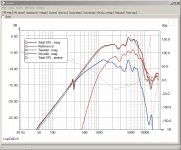
I agree, the curves are ugly..
They are with the raw responses and the x-over (as buildt), no level adjustment between drivers.
I just used this to throw in a series cap with the tweeter to see what happened.
Based on this, I decided to throw in a 12,9 uF cap I had, thus giving me some tweeter protection and at the same time smoothing out the tweeter response a bit.
I've now taken some raw measurements with the cap in place and I'm working on getting this in to Lsp Cad as per 5th's instructions! 🙂
Once that is done, I'll hopefully be able to tweak the x-over to get some workable results! 🙂
I must say that this software seems very usefull, will certainly save me from trying and failing a lot, not to mention wearing out the solder-pints on my board! 🙂
It doesn't look like this thing ever stops.. seems like it gets to a point where it gets fairly close to a target response and then just keeps mkaing minor itterations. perhaps this happens because it runs out of range on certain components?
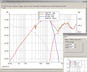
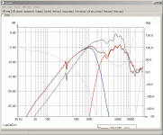
here's a plot with the drivers raw responses, the total raw response of the speaker (grey) and the summed driver raw responses in red.
Looks like the summed and reference plots agree pretty well.. tried to adjust woofer/ tweeter positions in the Z plane but that seemed to do little and did not improve the match between the plots.
allso tried to adjust the woofer position in the Y plane corresponding to its baffle placement relative to the tweeter, but this gave for a lesser match between the target and summed curve.
Annyway, I assume that the repsonses now upploaded in LspCad are suitable for further work optimizing the filter slopes.
Attachments
Yeah it never stops because nothing ever tells it to. The step size governs how much it will change any given component value per iteration. To that end you can set the step size higher at the start of an optimisation process and then, once the curve fits decently, you can reduce it to get a better fit.
If you want to try a different measurement program you can give ARTA a go. I've used Holm before myself and although it can do what ARTA does, ARTA is easier to use, especially when setting your gate and making repeat measurements.
If you want to try a different measurement program you can give ARTA a go. I've used Holm before myself and although it can do what ARTA does, ARTA is easier to use, especially when setting your gate and making repeat measurements.
Hol impulse seems to work quite nicely for me, and since I've allready got it up and running with a mic calibration file and everything, I guess I'll stick to it for now! 🙂
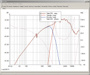
Just did the LP section ,entering a target of 1600Hz 4th order LR, locked the level to -5db and set the range to 500-5000 Hz.
Seemed to do the job quite nicely?
I allso added some gain to the woofer to bring it up to level with the tweeter.
Now I'ts time to see if I can get a HP slope for the tweeter that will sum with the woofer..
Attachments
Last edited:
- Status
- Not open for further replies.
- Home
- Source & Line
- Analog Line Level
- Shelving 2nd order high-pass?