Leap 4.5

I own a copy of Leap 4.5 including a physical dongle which connects to a pc serial port. I haven't run it in many years, but so far as I know it will still run on an old pc I own that has a serial port for the dongle.

I am concerned that in the future I may no longer be able to run this program if the dongle fails of if my old pc towers fail & I can't find a pc with a serial port or some way to add a serial port to a newer pc.

I know that the creator of Leap, Chris Strahm, is no longer with us and that no company appears to be selling any version of Leap anymore.

So, I wonder if there is anyone who may have a copy of the source code and/or a version of Leap that no longer requires a dongle to run??? If you know of anyone who might, please give me the contact info and I will contact him.

I may try to get my copy of Leap running in a virtualbox virtual machine running windows xp if I can get it to recognize the dongle and if I am lucky, I may be able to keep a copy of Leap that will forever run inside virtualbox since I do remember that if I start Leap with the dongle present, I can remove the dongle once the welcome screen is shown and Leap would forever after run fine with no dongle plugged in and therfore if I can essentially take a snapshot of Leap at that point inside a virtual machine and save that state in a file I can always load in the future inside the virtual machine, I ought to be good to go. But I have no idea right now if I can get that scheme to work.

I have not run Leap in a long time and it is for now stored away, but I do remember that Leap would model a lot of things such as mutual impedance between drivers and ports, nonlinear magnetic behavior near xmax, nonlinear behavior of the compliance, nonlinear behavior of voice coil inductance, and voice coil heating under strong loads, losses in the box/ports/etc, etc.

Will Vituix do any or all of that too?

Is there anything of major importance that Vituix does that Leap did not do?

Are there any other woofer/subwoofer enclosure design programs that are as good as and as complete as Leap was that I could also consider using for low frequency enclosure design?

Thanks very much for any help you can provide.

Sony TA-E88B Preamplifier Restoration

Hi all,
Well I’m off starting another restoration, this time the Sony TA-E88B preamp. I’ve noticed a few people have started threads or commented about this preamp, but they either petered out or didn’t get the info they needed. Hopefully I can create a useful thread that will help people in the future and I would really appreciate any feedback, comments and information you’re willing to share, to help me and others along the way!
This preamp is absolutely amazing and beautiful in its construction. It has a decent phono stage by all accounts and looking at the schematic it certainly seems to be the case.
Unfortunately, due to its age it’s almost definitely had a few different sets of hands digging around inside and I keep finding more and more little issues or things people have done, for reasons I am yet to find out. Luckily it was basically running when I bought it, so all the work I’m doing is to ensure its longevity, pretty it up and make sure that any bandaid fixes or mistakes are removed and repaired.
I have included a couple of photos below of about when I started working on it. I got part way into things before I started properly documenting, but you get the idea. I have some questions about alterations that were made, that are a bit beyond my level of knowledge, but I’ll post about that next so I don’t end up writing more than anyone wants to read in one post!
Lastly, if anyone has any documentation like the original user manual or any supplementary documentation other than the service manual, please share, it would be a great help.
Thanks in advance for any contributions.
IMG_4394.jpeg

IMG_4150.jpeg

DACmagic plus outputs only high pitch noise

Hello everyone,


I've been using dacmagic plus for about 4 years, however I bought it used so I don't know how old is it. Since last 3-4 weeks it does'nt work properly. When I turn it on and when there is a input signal, it only produces a noise. When it happened for the first time I let it on for 15 minutes and selected an empty input, then I selected my usb input again and turned it off and on. It started to work properly. But when I turn it off again it made the same thing. Now waiting 15 minutes or even longer such as 24 hours doesn't work, it only produces high pitch noise. I tried different inputs as well, usb-PC, optical-PS4, Bluetooth-Phone but the result was same.


So I think some caps went off but I have no idea. If it is something like that I can solder new caps but I don't know how should I tackle this problem. It would be great if someone could help? Thanks in advance.

Here is a video of what happens:

YouTube

Speaker connector terminals (crimp)

Hi
Rookie question.
I'd like to use an existing speaker cabinet to test various drivers. The existing crossover has solid wire going to the speaker terminals and terminates by soldering.
I'd like to use crimped speaker terminal connectors for speed so I don't have to desolder and solder each terminal. Main reason being the height of the driver location makes soldering challenging.
There are these quick attach terminals or the basic crimp terminals.
https://a.co/d/3PyxaUd
https://a.co/d/etbHaod
However it is my understanding that crimping solid wire is not advisable.

Foam Core Board Speaker Enclosures?

Has anyone tried using foam board (paper laminated with foam core) as quick and dirty speaker enclosures? There is something really satisfying in using nothing more than an x-acto knife and a hot melt glue gun to build transmission lines, horns, etc to try out designs on smaller 3 in and 2 in low power full range drivers. Interestingly, they actually sound pretty good and weigh nothing compared to mdf. I am just wondering if I am the only trying this sort of stuff before cutting real wood. My latest build is a stereo pair transmission line that is very flat and hangs like a picture on a wall. Lots of fun and very quick and clean. The foam core actually has built in damping capabilities. I do find that it sometimes resonates like a guitar body but that is not necessarily bad.

I am editing this first post to show what is possible with foam core and hot melt glue - the elusive Cornu spiral horn.... Read on if you are interested in this wonderful speaker and have a day or two to try building it.

For folks in France, FC board is called "carton ou de mousse"

Erreur 404

In Germany, try here:

Attention Required! | Cloudflare


Index:

Cornu spiral BLH original vs Smooth Curve Ever think of building a Cornu Spiral horn? Now you can! - Page 3 - diyAudio

pdf plan for Cornu spiral by Planet10 can be found here: Foam Core Board Speaker Enclosures? - Page 23 - diyAudio

Micro 14in Cornu with 2in driver from Logitech S120 (Dec 2012):
Ever think of building a Cornu Spiral horn? Now you can! - Page 6 - diyAudio

Flat wall mount stereo MLTL with Vifa TC9FD http://www.diyaudio.com/forums/full-range/223313-foam-core-board-speaker-enclosures-147.html#post3400954

Flat BIB or FIB with Vifa http://www.diyaudio.com/forums/full-range/66173-terry-cains-bib-why-does-work-does-anyone-have-those-fostex-craft-handbooks-516.html#post3344893

FIB alternate without V channel http://www.diyaudio.com/forums/full-range/66173-terry-cains-bib-why-does-work-does-anyone-have-those-fostex-craft-handbooks-512.html#post3339813

Folded bookshelf MLTL with Vifa http://www.diyaudio.com/forums/full-range/232778-fostex-fe83en-right-small-box.html#post3427671

FH3 Inspired Floorstanding Back Horn with Vifa FH3-inspired Foam Core Mini Build and here http://www.diyaudio.com/forums/full-range/227460-fh3-inspired-foam-core-mini-build-3.html#post3339779

Mini Karlsonator (0.53x Scale) with dual Vifa TC9FD's http://www.diyaudio.com/forums/full-range/237948-speaker-kicks-butt-large-spaces-21.html#post3560234
http://www.diyaudio.com/forums/full-range/237948-speaker-kicks-butt-large-spaces-21.html#post3560234

Mini Karlsonator (0.4x Scale) with single Vifa TC9FD
http://www.diyaudio.com/forums/full-range/239338-mini-karlsonator-0-53x-dual-tc9fds-16.html#post3722988

Nautaloss spiral sealed-end TL Reference Monitor (200 Hz to 20 kHz) with Vifa TC9FD
The Nautaloss Ref Monitor

Teardrop Shaped Sealed Monitor (200 Hz to 20 kHz) with Vifa TC9FD
http://www.diyaudio.com/forums/full-range/223313-foam-core-board-speaker-enclosures-208.html#post3739273

Nautaloss sealed quad driver push-pull sub: http://www.diyaudio.com/forums/full-range/247598-nautaloss-ref-monitor-6.html#post3750186

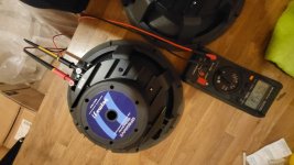
XPS Foam & Foam Core MLTL using PE's 6.5 in Polycone Woofer (Buyouts): http://www.diyaudio.com/forums/full-range/223313-foam-core-board-speaker-enclosures-210.html#post3755545

The simplest FC speaker ever - "The Dual Exciter OB Cheap Thrills" speaker: http://www.diyaudio.com/forums/full-range/223313-foam-core-board-speaker-enclosures-225.html#post3840132

Dual Chamber Reflex with Curvy Walls - Viva la Vifa! - nice desktop monitor speaker:
Viva la Vifa! Curvy Cabinet DCR with TC9FD

Single Speaker Stereo (SSS) - matrix 3 channel:
http://www.diyaudio.com/forums/full-range/223313-foam-core-board-speaker-enclosures-239.html#post3961261

A real 40 Hz (-3dB) 113dB SPL capable sub woofer (slot loaded band pass) that weighs less than a pound (excluding driver weight):
Light as Air Slot Loaded Band Pass Sub

A 175Hz 28in wide x 17in tall x 22in deep tractrix horn for the 5MR450NDY, a full range horn capable of 300Hz to 15kHz and +125dB:
http://www.diyaudio.com/forums/full-range/259293-prv-5mr450-ndy-fast-applications-10.html#post4033969

A tractrix synergy horn - the Trynergy, the best sounding speaker I have built out of foam core to date. Perhaps my most ambitious speaker but surprisingly easy to build:
http://www.diyaudio.com/forums/full-range/261427-presenting-trynergy-full-range-tractrix-synergy.html

The Hypercube speaker with a TC9FD - nice 150Hz to 18kHz speaker good for HT satellites or desktop FAST:
http://www.diyaudio.com/forums/full-range/265053-hypercube-loudspeakers-12.html#post4128571

Mass-damped Hypercube with PRV 5MR450NDY - 250Hz to 15kHz 95dB sensitive tops for a FAST:
http://www.diyaudio.com/forums/full-range/265053-hypercube-loudspeakers-27.html#post4134697

Lance TL with RS100-4 (Dec 21, 2014):
http://www.diyaudio.com/forums/full-range/223313-foam-core-board-speaker-enclosures-255.html#post4159850

DCR stereo Bluetooth speaker with RS100P-4 (Jan. 6. 2015):
http://www.diyaudio.com/forums/multi-way/267585-project-big-bluetooth-spkr.html#post4176790

The Dagger short TL - a very open sounding hifi FAST top (Jan 20, 2015):
http://www.diyaudio.com/forums/full-range/268037-fast-tl-8.html#post4192688

XKi - X's ab initio Karlson 6th order band pass with RS100 (Jan 24, 2015):
http://www.diyaudio.com/forums/full-range/268524-xki-xs-ab-initio-karlson-6th-order-bandpass.html

XKi - Dual Tangband W5-876SE subwoofer (Feb 16, 2016):
XKi - X's ab initio Karlson 6th Order Bandpass

KaZba (Karlson aperture Z-baffle) Dipole FAST (March 25, 2015):
http://www.diyaudio.com/forums/full-range/271011-rockin-kazba-dipole-k-aperture-z-baffle-dipole.html

10F/8424 and RS225-8 FAST Ref Monitor (April 24, 2015)
10F/8424 & RS225-8 FAST Ref Monitor

XKi with 5in Dayton PA130-8 (Aug. 23, 2015): http://www.diyaudio.com/forums/full...arlson-6th-order-bandpass-33.html#post4428603

Plans for Daytonator here: http://www.diyaudio.com/forums/full-range/268524-xki-xs-ab-initio-karlson-6th-order-bandpass-32.html#post4404251

FF105WK TL with trapezoidal curved baffle (Sept. 8, 2015): EVA foam for performance speaker enclosures and here
FF105WK TL for Desktop/Bookshelf

0.44x/0.55x Wide mini Karlsonator for FE103 - works great with RS40-1197 and CHN-70 (Sept. 23, 2015): http://www.diyaudio.com/forums/full-range/239338-mini-karlsonator-0-53x-dual-tc9fds-154.html#post4458490

FR58EX/AC130F1 micro FAST (Sept. 28, 2015) - uses a foam core Dagger for the full range mid/tweeter: http://www.diyaudio.com/forums/full-range/239338-mini-karlsonator-0-53x-dual-tc9fds-154.html#post4458490

Wall Mounted A7.3 MLTL (Oct. 4, 2015): http://www.diyaudio.com/forums/full-range/260758-full-range-wall-home-theater-10.html#post4472884

PMC inspired TL Monitor with DC28F and DC130A (Oct. 30, 2015):
Low-Cost PMC-inspired TL Monitor with DC130A and DC28F

GR Research X-LS 2-way speaker (Dec. 5, 2015):
Foam Core Board Speaker Enclosures?

Micro Trynergy with SB65WBAC25 and dipole bass (Dec. 22, 2015):
Presenting the Trynergy - a full range tractrix synergy.

Curvy wall Tabaq with P830986 (Dec 23, 2015):
http://www.diyaudio.com/forums/full-range/88787-tabaq-tl-tang-band-119.html#post4556798

XPS 10F/RS225 FAST TL (Dec 22, 2019):
10F/8424 & RS225-8 FAST / WAW Ref Monitor

Nano Trynergy tractrix point source with RAAL ribbon and 3FE22 (Apr. 20, 2020):
Nano-Trynergy - a Compact Tractrix RAAL Ribbon Point-Source Horn

Homage to LS3/5A (August 23, 2020):
RST28F and DC130A Foamcore Homage to LS3/5A

Help finding speaker stands for my KEF C55

Hello guys

I was wondering if any of you would have suggestions about where to find some speaker stands that would match my KEF C55 (around 25cm square footprint) without breaking the bank, and without going into the chinese plywood crap that seems to be everywhere...

I have looked at various places and did not find anything not being uncomfortably small like laser cut monitor stands, or too big and chunky like the bigger chinese stuff...

I'm looking for something that would be stable, discrete and allow to mop the floor without ruining the speakers wood...

If anyone has some clues where I could find something decent enough I would be very thankful 🙂

For Sale (12) Dayton Audio PA380-8 15" Pro Woofers

Update as of 12-23-24: I have (4) remaining Dayton Audio PA380-8 15" Pro Woofers for sale in the Santa Fe / Albuquerque area of New Mexico.

This driver is an excellent budget pro woofer: 3" overhung coil with 5mm linear xmax, 500W thermal ability, accordion edge surround, low Q, very high BL, low Fs. They work really well in large, vented enclosures or even a rear loaded horn or transmission line and have excellent sound quality.

These drivers were kept in a climate controlled, non-smoking home theater. They were used in active subwoofers, driven by Crown Class D amplification. They have always seen clean power and were never over-driven or abused.

They are in perfect condition, both functionally and cosmetically. I can provide impedance plots for any of them if requested. Photos as well.

$160 for all four + shipping

Each is packaged in an OEM woofer carton.

https://www.parts-express.com/Dayton-Audio-PA380-8-15-Pro-Woofer-295-034?quantity=1

Steve in NM

Attachments

  • 295-034-dayton-audio-pa380-8-specifications-46884.pdf
    295-034-dayton-audio-pa380-8-specifications-46884.pdf
    279.2 KB · Views: 62
  • 2024-07-24_070528.jpg
    2024-07-24_070528.jpg
    324.3 KB · Views: 81
  • 2024-07-24_070616.jpg
    2024-07-24_070616.jpg
    194.4 KB · Views: 94
  • 2024-07-24_070642.jpg
    2024-07-24_070642.jpg
    256.7 KB · Views: 89
  • 2024-07-24_070714.jpg
    2024-07-24_070714.jpg
    280.9 KB · Views: 96
  • 2024-07-24_070736.jpg
    2024-07-24_070736.jpg
    319.9 KB · Views: 84
  • Like
Reactions: taloyd

My impedance curve measurement does not match that of B&C speaker

Hello,

I'm building two subwoofer boxes. I'm using 18NW100 8ohms. When I measured the impedance curve of the set (box/subwoofer) I noticed that the tuning was lower in frequency than the subwoofer resonance. So I decided to measure it alone. And it gave me a resonance at 41.7hz when the datasheet says 31hz. I don't understand. Any ideas? thanks!

From Fresno CA

I'm retired and getting back to designing and modifing loudspeaker systems I spent some time at DWD loudspeakers in the "70s. Then on to rock and roll systems. Opened a shop in Fresno called Clearwave Audio building surround sound speaker systems for the UA Cinemas. Had to close down because Peavey bought the rights and made me stop. (never do a handshake agreement with friends) Moving on, I finally became a logistics and designer of (Big!) tradeshows for Pelco (was Schneider Ele.) Now finally I have the time to give Loudspeakers another try. Way back in the early '80s I had a Apple IIe with PRODOS running SDS loudspeaker design software. I still have all the floppies and manuals! I still have my LinearX LMS and the dongle for LEAP along with a couple of old pentium processor PC. Maybe I'll get lucky and all will install smoothly (DOS 6.22).

What tube socket for 845 tube

Looking to update sockets in my amp and considering these two options:
1. NOS RCA UT-541-C: https://reverb.com/item/81872688-ra...ca-ut-541-c-ceramic-tube-socket-brand-new-nos
2. Or these from AliExpress: $51.99 | EIZZ High Quality 4pin Jumbo Tube Socket FU-5 810 211 805 845 Valve Tube Base Hifi Audio Vintage Tube Amplifier DIY 1PC
https://a.aliexpress.com/_mOh4d9D

So basically NOS USA bayonet style socket vs new Chinese regular pin socket. The ones from aliexpress have a PTFE variation, that I think is better than ceramic. I know that Aliexpress can be a gamble, but on the other hand it is not like it is a rocket science to make a socket 🙂. What do you think?

For Sale LM391N-100

I've purchased a while back, last stash in a closing down repair shop in germany. Got it for my first love, telefunken ta-750 as a means to extend it's life but i won't be needing more than four in my lifetime. So i'm selling the rest four pieces. It was kept as bought in antistatic bag on an antistatic sponge.

Price is 15€ per piece + shipping, PP.

Attachments

  • IMG_20241216_183513.jpg
    IMG_20241216_183513.jpg
    314.6 KB · Views: 51

Pluvia 7HD cabinet recommendations

Hi all,

I built a pair of DIY open baffle speakers using a Pluvia 7HD full range driver together with 2 Peerless 12 inch drivers for lf. I would like to keep things as simple as possible, and I don't like the need for a seperate DSP and two power amplifiers.

So I was wondering, if there exists a well performing single driver Pluvia 7HD design? I'm aware of some free plans on the Mark Audio website. But how about lf-range for such a small driver? I don't need very low lf range, but I guess it should at least reach about 60-80 Hz (-3dB) to have some acceptable lf? Any suggestions about which design would be suitable? Or should I get a bigger driver?
  • Like
Reactions: sdsddsd1

Hello from Puget Sound Washington State USA... My name is Rich and I am addicted to building guitar effects pedals and tube amplifiers

I started down this (obsolete valve technology) rabbit hole many years ago. It all started by building guitar effects pedal kits. From which I learned good soldering and de-soldering skills along with how to use a good multi-meter. I now have two which saves a lot of time. This led to total addiction; so don't get started.

I have now built well over 50 pedals. And, now I make them for musician friends. This is also a slippery slope, because then you get asked to fix an amp, so you do and the next thing you know is just how much you DON'T KNOW.

I have now built four Fender 5E3 Tweed Deluxe clones with and without mods, a Tweed Bassman and Tweed Bandmaster. I have repaired, restored and re-cabbed another half dozen or so CRATE's, Marshalls and MESA's.

At the moment, I am trying to find a ground fault in a DIY Tweedly Dee simultaneously I am working on trying to build Dr. Z's Route 66, a Tweed Tremolux and Dave Hunter's 2-Stroke.

I am here to share my experience when appropriate and learn from those with greater experience in the crazy world of vacuum tube/valve amplification.

I hope to get to the point where I can build a stereo amplifier and play some old vinyl.

Philips amplifier 22AH309/00 : which kind of output connection is this?

Dear Community

I own a Philips lab stereo with amplifier model “Philips 22AH309/00”
Now, on the front of the amplifier, I can select 2 outputs/speakers: A or B.
I always connected a couple of speakers inserting the speaker pins in the A plug (see the attached image)

But I’m wondering: which kind of connection is the one marked with B? I never seen it before.
How do I plug speakers in to that B plug?
And if I do, will I be able to play on 4 speakers at the same time?

I tried to surf the web for this, but not even knowing the name of that input, it’s a hard search...

Thanks!

Marco

Attachments

  • IMG_0634.jpeg
    IMG_0634.jpeg
    218.5 KB · Views: 86
  • IMG_0635.jpeg
    IMG_0635.jpeg
    484.4 KB · Views: 73

DIY Sound Card with tape emulation

Hello everyone. In my last discussion, I was looking for ADC/DAC converters for my console. But as I was told, it is too difficult to create such a device and it is easier to buy a ready-made device. But it occurred to me that if we leave the principle of completely analog mixing and record only the output from the console adder, that is, assemble only the ADC stereo to record L/R Mix. But in addition to the banal converter, you want to add notes of tape recorder operation or assemble a preamplifier with emulation of the amplitude-frequency characteristics of some studer. Block scheme of operation of such a device: console output > preamp+emulator > ADC > USB cable to PC. It doesn't work in the opposite direction either, because there is simply no reverse side. I need to make sure that the mix from the console with processing immediately goes to the computer in daw. And I will do further operations, such as cutting the material and minimal post processing using my focusrite solo. I will be glad to read and maybe get ready-made ADC converter circuits with usb output, as well as with drivers. I would also like to find studer or Sony preamp circuits for tape recorders that I could use in this device. I will be happy to read about film emulation and tape movements, how to make them with the help of wiring circuits and not plug-ins. Thank you.

Reflow on a Sonus amp

I'm using a dead Sonus amp as a practice piece so I can learn some reflow techniques. I have a hot plate made to preheat boards and a reflow hot air gun. I tried 140C preheat and 400C hot air and nothing comes close to liquifying the solder. Even my manual iron had difficulty melting the solder on most of the components. Do they use some really high-temp solder or is it just the run of the mill non-leaded stuff and I just need to persist? Suggestions please!

Recapping Meridian 557

Hi,

I'm starting on a recapping project on my Meridian 557. I am a EE/CS and have done lots of systems work from prototypes to production commercial control systems, computers, etc. However, I haven't done that much work on hifi amplifiers and I've never tried to remove an amplifier board from a 5 pound heat sink.

On the 557, the main circuit board (similar to the Alex MM circuit board in "The Very Best Amplifier I Have Ever Heard" thread) has 4 power transistors (Toshiba 2SA1302) on the top and 4 on the bottom configured to lay flat on a heat sink that the board is attached to. Each of these power devices has a very thin custom square of heat tape attaching it to the heat sink along with a single hex screw. My main question is whether anyone can provide the best process for removing and reattaching these power transistors to the heat sink so I can flip it over to remove/replace the caps. There are other devices on the heat sink, some with heat tape, some with thermal compound but the power devices are the only problematic ones.

Thanks,

D

Big mess - Bought an unfinished project - 3way ScanSpeak/SEAS active floorstanders on Hypex amps - where to begin....???

Hello everybody!

As mentioned aready in the "Introductions" subforum - I'ts my 9th year here, but without writing anything... and the time has finally come 😉
I was always more into car audio. Where from one point of view active systems are even more common, but from the other I never got so deep into it as I need now.

I'm a Scan-Speak fan. Used Revelators in a few of my cars (still using in current one). Have a DIY Revelator 15W (+HDS tweeter) monitors as "PC speakers" wich I built myself based on this project from user @gornir

https://www.audioexcite.com/?page_id=59


Lately I came across nice floorstanders built on D2905/990000 + 15M/8631G00 (10l ported) and Seas CA25RE4X/DC (~60l ported) as a woofer, all ran from Hypex FA253 amps.
As they were in a bit of "unfinished project" state - no veneer (just painted plywood) and also no really properly designed/tuned x-over - the price was an absolute steal.... I just needed to have them.... 😉

jpeg01.jpeg


I did some listening sessions. Did some (room?) measurements with REW and UMIK. Did some tuning. I'm even starting to be a bit happy with them but I know that all of it it's just wandering in the dark
jpeg02.jpeg


I know how to use active crossover systems, I know a bit about measurements (not much but at least how to run/start them)
Once I had the Behringer 8000 mic and some phantom power XLR usb interface from M-Audio but I did sell it a long time ago.... Currently I have the UMIK1 USB microphone and access to some software but will it be enough?

In addition... I moved to a new house some time ago and my room is still untreated I'm working on it now) but even after the treatment....
jpeg03.jpeg

jpeg04.jpeg


I'd like to get into it as properly as possible... My main questions are.... Where should I begin (to read/learn)? Which way to go? Can I try to design a 3way crossover in a livingroom? Is my equipment enough? (If not) What should I buy? Or maybe I should try to design it in Virtuix CAD? I'm so so confused...

Thanks for any help
  • Like
Reactions: motokok

Low noise bipolar transistors for audio?

What are some good low noise bipolar transistors with good linearity?

9014's claim a 0.9db typical NF. but there's no noise chart.
they seem to be very similar to 2n2222's which also have around 0.9db NF.
2SC1815's meanwhile show a 1db NF and no chart. and they're far less linear too.
2SC1845's seem to have less noise, or are they just a HV version of the 2SC1815?

Audio signal

Good day, new member here from South Africa, need some help with a small project I'm busy with, I've got a small Bluetooth speaker that I've stripped and I'm Rebuilding it, I've added 2 additional amplifiers as I've added extra speakers and increased the battery capacity, but that's not the problem, everything works besides the fact that I need a clear audio signal for the additional amplifiers I've added, is there someone here that can maybe tell me where on this pcb I can get a clear signal? I've added some photos, thanks.I need a L,R and a ground.

Attachments

  • IMG20250105175132.jpg
    IMG20250105175132.jpg
    313.7 KB · Views: 40
  • IMG20250105175140.jpg
    IMG20250105175140.jpg
    295.5 KB · Views: 39

Unusual amp from 1987

I found this amp in old Radio magazine (in Russian).
It looks interesting (Vbe multiplier arrangement, VAS),
so I tried to sim it. The results don't look bad.
Has anybody seen a similar amp before?

I had to make some changes (hopefully 'improvements'),
as the original amp was clipping too soon, and bias settings
couldn't be made to work..
Sim files with models attached.
===========================


Update: This thread continued with similar amps to this one, namely Wiederhold amp from 1977, and its derivatives.
What's common to all of them is: op-amp input and folded cascode VAS.
As of Jan 2024, based on this thread, over 15 amps have been 'officially' successfully built and tested (plus several prototypes).

1) Posts #87, #117, #136 - LMK (Lomakin & Parshin) complementary BJT
2) Posts #172, #201, #206 , #1449 - complementary LatFet Wiederhold77
3) Posts #326, #313, #1735 - quasi HexFet Wiederhold77
4) Posts #952, #985, #1065 - quasi BJT Wiederhold77 with 2n3055 devices
5) Thread LatFet Amps Based on Philips AH578
6) Post #1537 , #1471, #1568 - high power and improved version of LMK amp with FQA vertical mosfets (3 pairs)
7) Post #111 (in another thread) - high power symmetrical LMK-type amp with Philips AH578 input stage
8) LMK-type with Groner input stage built in April 2022
9) Alexander-type amp with folded cascode VAS - post #1676
10) Darlington-type VAS - post #1699
11) Post #1706 - LMK complementary BJT with TIP3055/2955
12) Post #1709 - Hafler P7000 inspired amp
13) Post #1736 - mirror VAS with interesting compensation
14) Post #1735, #1744 - quasi HUF logical level fets Wiederhold77
15) Post #1745 , #1746 - 'improved' Hafler P7000 with (Hawksford Cascode)
16) Thread Fast Mosfet amp with LT1223

Attachments

  • radio_amp1.png
    radio_amp1.png
    70.1 KB · Views: 9,543
  • radio_amp1_thd.png
    radio_amp1_thd.png
    34.4 KB · Views: 10,197
  • radio_amp1_fft.png
    radio_amp1_fft.png
    18.4 KB · Views: 10,085
  • b.1987-09.038.jpg
    b.1987-09.038.jpg
    676.5 KB · Views: 8,604
  • radio_amp_1987_09.zip
    radio_amp_1987_09.zip
    14.1 KB · Views: 1,096
  • Like
Reactions: chermann

Chip Amp For computer speakers

I am looking to build an amplifier for a pair of Fostex BK-40h fullrange desktop speakers. Initially, I was just going to buy a dayton DTA-1 but that's boring.
I am considering building the non-inverting gainclone described here on some perfboard as it is very simple and does not seem to require a lot of heat dissipation. Are there any other amp designs or gainclone variations that I should consider?
Thanks.

6AK5 amplifier as add-on for digital oscilloscope

Hi,

I have ATTEN ADS 1062CML 60MHz 2-channel digital oscilloscope and it has a major problem - poor input sensitivity. Some applies to other consumer grade digital oscilloscopes with cost price around several hundreds USD or Euro. By a chance I found in very old Radio-Electronics magazine low-noise (300 uV output noise with input shorted) high-sensitivity amplifier based on 6AK5. Frequency response 5Hz - 1 MHz, amplification factor 100, max input voltage 0.25V. Amp is immune to high-voltage overload typical for vacuum tune circuits. I powered it from 4 x Li-ion 18650 batteries with nixieclock.org NCH6100HV (12-24V input, 85-235V/24mA output) buck step-up converter and LM317 for 6.3V filament. Both available on Aliexpress.

Article in PDF format and LTSpice files (original schematic and my mods) enclosed in ZIP archive.

I assembled original schematic on prototyping board and it didn't worked as expected, it oscillates no matter what. Additional symptom was low plate voltage on first two 6AK5 (around 45 - 50V with B+ = 135V). Verified assembly many times, replaced NOS Siemens 6AK5 with 6Z1P, no changes. I suspected noise from NCH6100HV buck step-up converter but its not the case since amp is connected with C-R-L-C filter with electrolityc, film and ceramic capacitors.

Finally I have given up and brought this amp to my friend who have more experience. He modified screen grid bias (added R14 and R15 on LTSpice schematic) so voltage (on screen grid) is about 30-31V. Amp is working now. This all is quite strange since it was assembled in Radio-Electronics test lab and they confirmed amp data.

Anyone can comment this issue? Thanks in advance.

Attachments

  • Screenshot at 2024-12-31 20-50-11.png
    Screenshot at 2024-12-31 20-50-11.png
    915.5 KB · Views: 147
  • Screenshot at 2024-12-31 20-52-29.png
    Screenshot at 2024-12-31 20-52-29.png
    305.5 KB · Views: 132
  • LTSpice_Files.zip
    LTSpice_Files.zip
    669.4 KB · Views: 44

Tonearm bearing problem on Palladium NSP-730

Hello, some time ago I bought a Palladium NSP-730 turntable and gave it some basic TLC as you do with vintage TTs, and it worked, and I didn't give it much thought since. Recently, I noticed that on some records the inner groove distortion gets really apparent, and my cart adjustment were on point. I looked at the tonearm gimbal, and noticed that the arm is ever so slightly skewed at the pivot point, and it makes the arm not move perfectly horizontally, but ever so slightly upwards as it approaches the middle of a platter, causing the azimuth to go out of alignment the closer it is to the end of a record. How hard a fix this would be? I'm sure I'd need to disassemble the arm, what about bearing adjustments afterwards? Is it at all doable without a test record? Thanks for any input.

Attachments

  • IMG_20250105_131301704.jpg
    IMG_20250105_131301704.jpg
    130.4 KB · Views: 49

Power supply sizing question

Hey all, Got a question. I hope this is not going to start some kind of flame / war, open old wounds etc. This is a question driven out of curiosity and desire to understand!

Given an amplifier of M2X - so 25 watts per channel, 24 volts DC - Why do I need a 400VA / watt supply?

Assuming each channel is going to draw 25 watts - that means I should need 25 x 2 == 50 watts. Watts to volt amps is 1:1, they are the same as I understand it. Did I miss-understand something from the thread? This question should really apply regardless of the amplifier board - this should be mostly universal right?

I was talking with a friend of mine who used to do electronics design at bell labs. When I told him about the power supply he posed the question above to me - I had no answer. I was simply going on what I thought I understood from the thread - that people should buy for 400VA worth of 18VAC.

Thoughts? Are there docs on this - if there are I was not able to find it via google searching or in the forums that I found so far.

Cambridge CD2 new output stage

Hi Guys,

Finally got my hands on a CD2 thats mine and I want to change the output stage. I want to remove all the opamps and join all the connections and put it in a seperate preamp like class A.

The CD2 has 4x TDA1541 and I believe each DAC has 4ma output. Total = 16ma. I'm not sure what magnification the datasheet is, it has a 1.8k resistor across it.

I don't want valves as its beyond me and high voltages, transformers would be nice but its alien technology to me. So I was considering preamp boards, there seems to be plently from China that are Naim or other based that offer some form of magnification. Has anyone tried any of them with TDA1541 or reccomend anything? It is not enough magnification?

I plan to build an external housing with its own PSU. Thanks in advance for any info offered

Attachments

  • PXL_20241219_161717226.jpg
    PXL_20241219_161717226.jpg
    475.3 KB · Views: 99

Pepco Paul Guitar Amp AC wiring

I'm restoring this amp. It lacks a power transformer so I'm rewiring it with an isolation transformer. (A 3 prong cord was already installed)

I noticed that the volume control puts the excess signal to the mains?!?!? Should this go to ground instead?
Any other safety things that should be done to this amp?

I'm figuring the mains side of the isolation transformer is the side that should be switched and fused.

Attachments

  • PepcoPaul.JPG
    PepcoPaul.JPG
    176.7 KB · Views: 180

Starting a new Hi-Fi audio brand

Hi everyone,

I recently came across some old posts in this forum from people thinking about starting their brand in the Hi-Fi audio or loudspeaker industry. Since I have a similar idea, I have made this thread for those still thinking about this. Maybe we can exchange contacts and help each other.

My background as an employee includes 10 years of managing two small-medium-sized Hi-Fi and High-End loudspeaker factories in the EU. So, my core skills are deep knowledge of the market and production nuances.

It doesn't matter what region you are from or what background. If it's different, it might be even better.

It's nice to talk with anyone having the same passion and goals. Is it relevant for someone here?
  • Like
Reactions: rjbell

Now LTspice can run in mobile through winlator app Windows emulator.

Now it is possible to run lt spice in android mobile phone.
Download the winlator app file from github website and install lt spice & simply run it without any problem.
It worked perfect & smoothly.
Here are some prove.

Attachments

  • Screenshot_20250104-233322~2.png
    Screenshot_20250104-233322~2.png
    59.1 KB · Views: 92
  • Screenshot_20250104-233623~2.png
    Screenshot_20250104-233623~2.png
    52 KB · Views: 71
  • Screenshot_20250104-233551~2.png
    Screenshot_20250104-233551~2.png
    41.6 KB · Views: 61
  • Screenshot_20250104-233551~3.png
    Screenshot_20250104-233551~3.png
    41.6 KB · Views: 60
  • Screenshot_20250104-235307~2.png
    Screenshot_20250104-235307~2.png
    101.2 KB · Views: 72

Minimum Phase IIR filters require a large number of taps to be realized for low frequencies?

When I generate a *.Frd file with an IIR high pass filter(boost) and a FIR low pass crossover (125 hz) even with a high tap count. The low frequency is truncated instead of boosted. I thought the tap count is irrelevant for IIR filters. The same number of taps with just the FIR filter matches the crossover transfer function perfectly.

Soundstream Reference 404S

Hi everyone,
New here and looking for schematics for my most recent purchase, a soundstream ref. 404s. I had no luck googling for it.
Hoping to find the cousin of a friend of somebody's sister that has it lying around in the bottom of a drawer somewhere. PDF will do though.
Also advice wanted on recapping and what to look for in replacement capacitors. For my Rubicon amps I ordered mostly Nichicon FG, KW and KT series and Panasonic FC and FM. Was that a wise thing to do or is there more to a good match with a certain amplifier?

Cathode bypass calculator help

Hi,


Screenshot 2024-12-26 at 11.08.11.png


I have the following circuit and am trying to work out if I can get away with a smaller Cathode bypass capacitor on the 6c45 driver valve by calculation.


I managed to find someone quoting the plate resistance of the 6C45 at 2.5K and was using this calculator

But I got stuck on what the effective plate load is with the transformer, any help greatly received 🙂

Merry Christmas

Rich

Pioneer PD-10 - I screwed up, help!

Hi! I recently went and modified the analog stage in my Pioneer PD-10 SACD Player, here's what I did for clarification:
-Electrolytic caps replaced with Panasonic FMs and a couple Nichicons FW when I didn't have correct values of Panasonics
-OpAmps (5532) replaced with LM4562 (I haven't yet bypassed them, but I was planning to put a 100nf cap on them)
-Voltage regulators replaced:
-Positive 15V swapped from JRC 78M15A to LM2940CT-15
-Negative 15 swapped from JRC 79M15A to LM2990T-15
Positive 5V swapped from JRC 78M05A to LM1085IT-5.0

Here's what I KNOW I screwed up:
-at first, I put 2 positive 15v regulators instead of a positive and a negative
-lifted a few solder pads here and there, but none of them seem to be disconnected, so I just soldered over them and they hold in place.

The result is: noise. Just noise. Nothing else. The analog out just emits a hiss, doesn't react to any disc being played, any operation being done, it just hisses from the time I turn it on, to the moment I turn it off. It didn't change even after putting in the correct 15v regulators (I changed both positive and negative) and I don't know what to do next. I got my hands on a service manual, but I'm more comfortable working with it and the advice I get from people, so any help will be much appreciated. Thank you and have a good day! (Please somebody help)

24-Bit/192 kHz USB Audio Interface for vinyl A/D archiving?

There are several inexpensive 16bit/48kHz phono to USB 1.1 devices available to record vinyl to PC, but no one step solutions for higher res files. Would need at least a USB 2.0 interface. Wouldn't really need higher than CD quality for most LPs, but it would be nice to have options for those rare master quality records.

So far I've found a decent Schiit Phono preamp and been looking at USB home studio recording A/D USB converters that do 24-bit/192kHz. The weak link might be the A/D unit's built in preamps.

For Sale Populated cascode pcbs and empty aluminum pcbs for LU1014

I have for sale a few populated pairs of to247 cascode pcbs that can be used with those lu1014 that you are stashing 🙂
I can offer also the empty aluminum pcbs on which you will solder the smd jfet, a gate resistor and gate protection diode.
All gets joined with wires, I have bad experience with strip connectors and aluminium pcbs.
It lets you adjust the vds of the jfet with a trimmer.

30€ for 2 populated cascode pcbs
10€ for 2 empty alu pcbs

Schematic looks like this
444489ff-3394-43bc-9c1c-2a902362b525.jpeg


Modules and alu pcbs look like this. The wired module is not for sale.
IMG_0020.jpeg


I am getting great sound with these in my Gaincore amp.
IMG_9416.jpeg

Zetex parts, how good are they? How do these other parts compare?

Looking at my low noise high gain parts. Kind of the gold standard is the 2SC2240 and 2SA970.

the KSC1845 and KSA992 are definitely good, but not as high gain. How do the noise specs compare to the above pair?

BC550C and BC560C have the higher gain I was looking for, but again, how to the noise specs compare?

Now the pair that I question the most. I know that EW is a huge fan of these. ZTX694B and ZTX795A. Very high gain, I have seen them called low noise, but like the others I don’t know how they compare. Are there others that are fans of these devices? I just don’t see them getting recommended all that often, but maybe it’s because they are expensive? if the noise numbers are low enough, I would say these are a good competition to the 2240/970 pair.

Dan

Stage Accompany: the end or not?

Having surfed in the last few days on Dutch websites, it would appear that Stage Accompany, the Dutch factory responsible for the fantastic SA 8520 to SA 8535 planar tweeters (and other great gear) is undergoing bankrupcy proceedings (that's what announcements of public auction sales suggested). If that was true, it would be really sad unless they intend to re-establish themselves under a different name.

SA's website is silent about that. Does someone know more, perhaps some SA dealers or Dutch friends out there?

Chris.

LT1936 clicking noise ?

Hello friends , as i`m quite new to this voltage reg , is it normal for it to run quite hot , it is unpleasant when touching it ? Input voltage is around 10 V DC and the output stays at 5 V DC and it seems stable , but i do suppose that it oscillates somehow . It has been used for providing a PSU for the digital +5v of the Xylink transport to DAC and the reason why i do think it is faulty is because of the fact that first it is working fine but after some minute or more it is start to add clicking to the sound . How can i check this reg if it is working properly ? I have tried looking at the outputs with oscilloscope but found nothing ...

How to feed audio signal into the inputs of a TPA3255

Hi, i'm trying to design my own TPA3255 amplifier board, after seeing that most ones online are bad / terrible. One of those failed in front of my eyes for no apparent reason, while playing music well below the maximum power level of the IC (300W RMS x 2).

But i ran into a problem: i cannot understand how to feed the audio signal to the inputs of the tpa3255.

In the TPA3255 IC, there are input A, input B, input C and input D, but i dont know how to use them, i was expecting to find two simple inputs and a ground, like in the TPA3116D2.
But this one seems to be different.

Does anyone know how to use those inputs? Thanks in advance.

New Moving Coil Cartridge

Hi Respected Members,
I am Sacheen from India and new to this forum .

In the quest of enjoying vinyl playback to the maximum, ended up designing and developing a MC cartridge. I want to take it to the next level by bringing it out in the market.

Please suggest your views on what should be the approach to take it forward. Need to decide the pricing , marketing strategy and much more.
Eager for your expert opinion.

Approx. Draft Specifications
Output 0.3mV @ 1kz
Coil Resistance : 12ohm
Stereo Seperation > 28 db
Stylus : Elliptical on Aluminium cantilever
VTF : 1.75 to 2 gms
Static Compliance ~ 9.5x10⁻⁶cm/dyne
Weight : ~5.7 gms
Body : Dense Indian Rosewood body
Mounting : Threaded inserts for easy mounting and tight coupling with the headshell.

In search of the perfect sound or build a tape recorder.

Hello everyone. Today I breyed to my old tape recorder and decided to assemble my own. I know, it sounds crazy, but in general I don't see anything complicated in analog circuits (except for the tape broaching mechanism). So that's my idea. Make/or find drawings of the head block for 48-56 channels (erasing, recording and reading), order the heads at the factory, build a mechanism, control unit, and add preamps and correctors (to set up the tape recorder, you don't know phono correctors). Sony APR24, Studer A80, Studer A827 became the basis or ideal I strive for. I would like to be helped here in the implementation of the experience in the creation of such mechanisms. I would share in the discussion my experience in creating this particular model. I will also be grateful if you share the schemes from such projects. My idea is very interesting, but incredibly complicated. I will be glad if I can implement it with your help.

IR2104 not working with my Class D amplifier

I'm working on a class d amplifier at 300khz pwm at 0-5v and -2 to 2 v sine wave input, I've attached the schematic below for anyone who wants to have a look at it(please use the online simulator from infenion or else the schematic might not open) I understand this post is very vauge of me, but i just want some advice on how to continue and debug this issue
1735188328968.png

Attachments

I got Fostex FE206NV and a 2A3 amp...what enclosure should I build? Maybe something smaller than the Dallas II?

Greetings Friends. It's time to jettison the old Polks and build some speakers better suited to the low-watt amps I've been building. I have a pair of these Fostex FE206NV 8" full range and would like to build suitable enclosures for them. I'll be listening in my living room, about 12'/4m deep and 24'/8m wide, with about 6'/2m between speakers and the same distance to my chair.

Plans for Bass Reflex and Back-Loaded Horn cabs come with the drivers, but I'm more interested in the Dallas II design. It is a tad large and WAF is a factor at play. But I'm a pretty savvy cabinetmaker, if they're handsome enough she might go for it.

Are there any other designs I should know about? Perhaps in between the Dallas and the Bass Reflex they give?

Thanks for taking a look!

F-5 Turbo boards

This thread is for discussions about the F-5T clone boards. For more information on this product, please see the product page below.


Threads on diyAudio that relate to this product (If we have missed one, please post it in this thread and we will add it to the list):


BILL OF MATERIALS

The current set of boards available from the store comes in a set of 6 boards with the SKU of P-F5T-6V30 (that SKU decodes to "PCB, F5T, 6 pieces of revision 3 of the boards"). Please note that the fact it's revision 3 of the boards has nothing to do with whether you are making a V1, V2, V3 or V99 F5T and just means it's the third revision of the boards we've put out.

If you have P-F5T-6V30 boards and are making a V2 F5T use this BOM: F5T V2 (revision 2 of the F5T V2)

If you have P-F5T-6V30 boards and are making a V3 F5T use this BOM: F5T V3 (revision 1 of the F5T V3)

Note that the numbering of the silk matches the V3 schematic. The V2 just omits certain parts.

Variable Loudness DIY for Noob?

Hi. After an exhaustive search of this and other forums' discussions on loudness, loudness circuits, PCBs and kits and not finding much that I can understand, I conclude that I need some help.

I'm seeking a standalone variable loudness compensation control that can sit between my pre-amp and amp and can handle two channels and a sub. Preferably passive with a bypass switch. I've read through a lot of loudness threads here and on other sites and it has become apparent that I don't know enough to read a circuit diagram, understand how good of an implementation any given design is, how modify a design for my purposes and put a complete BOM together. My experience is limited to assembling kits with PCBs. Is there a kit for this somewhere? If not, does anyone know of a BOM? I might be able to figure out how to do this point-to-point or find someone to make a one-off PCB (if that's a thing).

Thanks in advance for any guidance you can provide!

Aaron

Component identification

Hello and Happy New Year!

I need help identifying a component in a Mirage M-290is crossover.
The component in question is the white block in the right bottom corner (first pic).
Anybody having the crossover schematics, by any chance?
I would like to upgrade the crossovers, to what extent should I go?
Caps are 4.7, 15 and 22..., currently Hanlan.
(will replace the steel nuts on the terminals, but the steel strips will remain, unless there is ingenious way to replace/bypass them )
Thx

Attachments

  • 20250103_141859.jpg
    20250103_141859.jpg
    442.8 KB · Views: 89
  • 20250103_141947.jpg
    20250103_141947.jpg
    562.3 KB · Views: 90
  • 20250103_142005.jpg
    20250103_142005.jpg
    430.3 KB · Views: 84

JAB5 Sigma Studio Wondom amp XLR help

Hi I built a DIY speaker earlier in the year and have used the Sure Wondom Jab5 4x100w amplifier with built-in ADAU1701 dsp. I have only ever used Bluetooth with it and it works perfectly fine like that and is great.

1000042768.jpg
1000042766.jpg


However recently been speaking to someone who had their own DIY speaker and asked if I had XLR input so we could connect them together. And they also said I could then also use that same XLR input to connect decks to my speaker if I wanted too. Which would be a great option!

I read on the sigma studio forum something about having to have a manual switch to toggle between Bluetooth and aux input. But it wasn't explained how to program that into the software. Also im unsure if aux and xlr would be different anyway?

Can anyone please help me in how to program sigma studio in order to accept a XLR input. I want to keep the Bluetooth input as well. Sigma studio itself i am still quite new to it, I have looked everywhere before posting here. I have added my sigma studio file for how i have it set.

Amplifier (there is also a wiring diagram photo) - https://store.sure-electronics.com/product/756

Attachments

How good are your ears?

Like for like I've probably listened to more speakers than most. My side-hustle is breaking speakers and selling the drivers. Like most of you I'm over 21 - my hearing is already past its peak.
Before I destroy a speaker system, I have the virtually unique opportunity to listen to them placed in an identical position, connected to the same amplifier as others.
In the modern era most of our music is compressed via MP3 or MP4a. If I'm being totally honest most of these speakers are much of a muchness - I can't often tell the difference.
My favourite bookshelves speakers (paired with a subwoofer) are manufactured by Sony.
As to the Brand of my favourites without a sub - I'm too embarrassed to say.
Rest assured, I have broken Mission, Yamaha, Tannoy, Peavey, Wharfedale and others.
  • Like
Reactions: camplo

Ciare 15 NDH 4S

I just got my hands on a set of Ciare 15 NDH 4S.

They will be used as subwoofers, covering up to 200 Hz.
The rest of the speaker system is placed directly on top of the subwoofers.

Normally, I prefer closed enclosures, but this time, I will go for a ported system.

I assume that a 10 cm port is needed, but do I need one or two, to avoid port noise?
Will there be any disadvantages, if I place the port(s) in the front…..it will make things easier for me.
An alternative is bottom fired ports.

Does anybody have an idea about cabinet size, port dimensions/length? I get variouse suggestions, depending of the calculation program used.

Greetings from Denmark, and thank you all very much in advance for your inputs.

Michael

Passive crossover close to the amplifier or driver?

Ok, so I had this idea from some time. Why to put crossover inside the speaker cabinet, while we can place it as close to the amplifier using the shortest connection available, and than run the signal for each driver separately, using separate cables for each.
I have mainly in mind 3 way speakers for separate 4-6mm cable for bass driver, but two ways could also benefit.

Are there any downsides of such solution, like power loss etc? Because I see only positive sides.
  • Like
Reactions: picowallspeaker

New here

Hi everyone!

I am a Sound Engeinneer in Montreal, Canada and currently studying in Sound Recording at McGill. I started gaining interest in electronics 2 years ago when I came across Moritz Klein on youtube who builds diy modular synths. Now I am working as a amp tech in a guitar shop and I am learning the wonders of tube technology. If anyone from Montreal would like to hang out, let me know!

Charles

Best commercial/kit speakers with affordable drivers?

I was feeling nostalgic about the Snell A/IIIs again, sorry, and one thing that struck me was that even for their time (mid 1980s) the mid and tweeters in those speakers were nothing remarkable. A middle of the road Vifa dome tweeter and 4" (I think) poly midrange, or coated paper. As hobbyists we constantly overspend money (well I do anyway) on drivers trying to outdo cheap commercial variants, but maybe the real trick is in the design and not the money spent on the drivers?

So I ask you fellow enthusiasts, you who have built and heard and bought speakers, are there speakers out there you wax poetically for which did not need to use the most expensive cutting edge technology to show the state of the art experience? What were your reference points? Convince us all that we need to spend less money on drivers. 🙂
  • Like
Reactions: Abhishmuk

Sansui AU-5900 Preamp Hiss noise and abnormal voltage

Hi everyone

I restored recently my AU-5900 that is replacing electrolytic caps, replacing small signal transistors and diodes , fuse resistors etc. I’ve done it in the past on the same model for few friends with success.

On the power amp side, result was ok will all voltage levels good and bias set up right.

However during testing I noticed that the quality of sound had degraded and specially got a background HISS noise on the speakers even if the volume is at minimum.

I further investigated and confirmed the noise being from the preamp.

I also noticed the following:

1. On F2604, the collector voltage of both TR03 and 04 was 6.7V in lieu of 9.2V as written in the service Manual. All other voltages on the transistors seem ok. Note on preamp I used KSC1845FTA and Nichicon KZ , ELNA silmics

2. On F2599, the voltage readings are somewhat lower at the outputs: 20.7V and -27.6V in lieu of 22V and -29V.
Please see in attached photo complete voltage measurements on the preamp voltage regulator.

For components on this regulator :
  1. A726 and C1313 was replaced with KSA992 and KSC1845
  2. E Capacitors was replaced with Nichicon KZ and FW type
  3. Zener diode RD-13EB was replaced with 1N4743A
  4. B526 and D386 replaced with A940 and C2073
All resistors checked ok

Could you please assist as I am really stuck with this since over a week.

I do not understand as I have checked again everything

Thanks and regards

AL

Attachments

  • 90349575-61e4-472a-8ab0-1aa97e097a2e.jpeg
    90349575-61e4-472a-8ab0-1aa97e097a2e.jpeg
    262.4 KB · Views: 87

Decreasing Sensitivity of Potentiometer-Based Sensor

I have a circuit with a 10k linear potentiometer that's used with the wiper resting at the central position. This is for a controller, and provides movement is either direction.

The problem is the first bit of stick travel away from center is too sensitive. The last half of stick travel in either direction is not sensitive. In fact, 75% stick travel left or right seems to be near 100% reading by the controller. The circuit that processes the exponential curve can't be reprogrammed.

I'm trying to find out if adding resistors in series with the ends of the tracks, or on the center wiper pin, or decreasing the resistance to either end of the track with resistors to the center wiper pin, or this plus a resistor on the center wiper pin would be a possible way to reduce this sensitivity without reducing the max reading?

Attachments

  • potentiometers.jpg
    potentiometers.jpg
    20.4 KB · Views: 309

For Sale Beyma 12P80NDV2.0

Have one pair of Beyma 12P80NDV2.0 for sale.
500€ + shipping. Notice my location, can ship anywhere in the world.
This is the original V2 with a smooth cone and triple roll surround.
Very light use, great condition.
Have been stored in a controlled climate.

There is plenty of threads on here with information on this driver for use in a 2 way or large 3 way setup.
Well behaved and extended smooth rolloff, easy to integrate with the driver above.
Very linear behavior to +/- 3,5 mm,xmax is stated in a realistic way.
Can take some power and works well with some eq on the bottom end.

Can be reconed with current 12P80NDV2 kits if the rise would ever arrive.

Will be packaged very well and shipped with tracking.
Fairly lightweight.

Attachments

  • 12P80Nd ribbed cone.jpg
    12P80Nd ribbed cone.jpg
    191.5 KB · Views: 71
  • 20240809_135618.jpg
    20240809_135618.jpg
    288.4 KB · Views: 64
  • 20240809_135631.jpg
    20240809_135631.jpg
    234.1 KB · Views: 64
  • 20240809_135719.jpg
    20240809_135719.jpg
    347 KB · Views: 58
  • 20240809_135912.jpg
    20240809_135912.jpg
    82.4 KB · Views: 58
  • 20240809_135954.jpg
    20240809_135954.jpg
    283.1 KB · Views: 57
  • 20240809_140022.jpg
    20240809_140022.jpg
    248.7 KB · Views: 64
  • Skjermbilde 2024-08-09 142417.png
    Skjermbilde 2024-08-09 142417.png
    277.8 KB · Views: 63
  • 12P80Nd.jpg
    12P80Nd.jpg
    140.4 KB · Views: 69
  • 12p80ndv2.0.pdf
    12p80ndv2.0.pdf
    308 KB · Views: 35
  • beyma.png
    beyma.png
    785.3 KB · Views: 70
  • beyma1.png
    beyma1.png
    272.1 KB · Views: 61

I am looking for a working circuit to create a 48/56 channel ADC/DAC board at a low cost.

Hello everyone! I own an English analog Soundcraft console and now that my favorite tape recorder has passed away, I decided to build my own converter for recording to digital. I'll say right away that the options on the market (ready-made) don't suit me for several reasons: price, functionality, and external layout. My console has 56 mono channels, 4 stereo channels, and 8 more groups, so I'd like to understand how the DAC/ADC works and build a custom one. I came across various schematics from Behringer for their DAC/ADC, but I didn't like the chip used in the circuit. Does anyone have experience in creating converters? Can you share your skills and schematics of ready-made single-channel converters (so that I can then install them in one case). It's also interesting to read about connecting to a PC. Installing cards into the computer itself is not an option (there are no free slots), and via USB is a good option, but if you remember the above idea of using single-channel converters, the question of combining them and transmitting information via one USB comes up. I will be glad to receive any useful information. Thank you.
  • Thank You
Reactions: Draki

Need help understanding some bits and pieces of a power supply

Let me start by saying my electronics skill level is at a very basic level. I have no formal training and what I do understand is self taught from reading and research. And help from forum members like you!

At this point in my project I am trying to understand some things on a power supply that don't make sense to me yet. Here is the board layout from the service manual:

Trace.png


It appears to me that some of the jumpers and resistors are not really doing anything. They are tied to the same trace circuit? What am I missing here?

Thanks!
Axis

Motor speed control

I've got a couple DC brushless capstan motors from a couple VCRs.

One requires a + voltage on the control pin to vary the motor's speed.

The other pulls the control pin up to 9Vdc.

I'd like to build a speed control circuit.

The motor that requires the + voltage may be easy as I can maybe use the control circuit I used with a VCR video head motor.

The motor that pulls the control voltage high has a control range of 2.133Vdc at 0 RPM to 3.70Vdc at max RPM.

The circuit I used for one motor.

Speed control final 4.png


Now if the voltage on the control line won't affect this circuit, I suppose that I could build the exact same circuit to control the speed unless there's a better circuit that uses the tach frequency.

The only thing is that circuit depends on the amplitude of the tach signal changing and both motors keep the tach signal at the same amplitude. Plus that circuit uses a transformer I cannot get anymore.

I used a variable power supply on the control wire and that works good so that circuit may indeed work, however the amplitude of the tach signal varies slightly once per revolution.

Drop in remote stepped attenuator

Hi All,

I found what I think is a neat remote stepped attenuator that is mis-described on AliExpress and Ebay and drops into the place of a large pot:

https://www.aliexpress.us/item/3256...t_main.11.363b1802RFjonO&gatewayAdapt=glo2usa

https://www.ebay.com/itm/145322085041

I prefer a remote volume control but typically want something fancier than a cheap motorized pot. The nice thing with these is that unlike a MUSES72320 kit or various other options, they drop in to the same physical space occupied by a standard pot in many preamps or integrated amps. If you want to run the display, it doesn't require as much hole as other options.

They are affordable (though they have gone up since the $43 I paid for my first one) and work on a USB supply (at least the two I got--though not the ones in the pics--say 7VDC but have a jumper where you can run them on 5VDC).

I've been looking for things like this for a while, but missed it for a long time because I typically search for attenuators. If I'm a goofball and misunderstanding this part, feel free to let me know.

Paul

Power supply for the class A headphone amp

Hi!

I am doing some diy class A headphone amplifier and would like to ask someone with more experience which power supply is suitable for my needs.

So the idea is to have two MeanWell smps modules with clclc filters feeding the regulator of some kind. The build will be small and compact - about 160x120mm


I have few ideas in my mind:

1. To have TPS7A47/33 regulators for each channel

2. To have TPS7A47/33 regulators feeding the super regulator (or kevin gilmore golden reference supply)

3. To have just super regulator (or kevin gilmore golden reference supply) with beefier filtering at the input.

4. Some better solution

Total current draw will be 300-400mA per rail and output voltage needs to be 20V.
I would like to know if regualtor output impedance has a big impact on the class A amplifier which is a farily constant load in comparison to other amplifier classes.


Any answer is appreciated.

MOD: Mini Output Delay - a headphone / line-level audio output delay retrofit PCB

BACKGROUND:
I needed to retrofit an audio output delay to an AC-coupled headphone amplifier design. The original protracted power-on transient of 6V would be enough to destroy some lower impedance headphone drivers. There are a few schematics available online, most of them had DC-offset protection too (something I did not require). For those who need continuously active DC protection, then Ti Kan created his e12 board. There are also solid-state implementations on these forums. Then this thread came to light discussing a circuit which seemed ideal with some additional modifications. However, the space available to me was absolutely tiny. I also wanted to shoe-horn this into other line-level pre-amplifier designs without compromising space. I finally came up with this tiny design:

FJe3GaG.jpg
ScA5U7r.jpg
WZ2u40h.jpg
sKc9NJA.jpg


DETAILS:
  • 29.2mm x 19.7mm 2-layer PCB.
  • 15v to 35V voltage input with voltage regulator. Optionally bypass voltage regulator for 12V input or to use different voltage relay.
  • Output delay adjustable up to 20 seconds with default build.
  • Relay is rated for headphone/line level - 0.5A 125VAC or 2A 24VDC.
  • Total current draw is 15mA.

SCHEMATIC:

m6fmCI1.png


BOM:
I sourced components from Rapid Electronics for a total cost of £2.83 (of which the relay is £2.22), which is a small outlay for considerable peace of mind. A more expensive Mouser cart is available: Mouser Electronics

JbBzoJ1.png


CIRCUIT DESCRIPTION:
IC1 is a small 12V regulator to power the circuit. The output delay is controlled by an adjustable RC time constant formed by TR1 and C3 [V(rc)]. As C3 slowly charges, voltage increases at the gate of Q1 which will eventually turn on the relay [V(relay)]. D2 is a 7.5V Zener which will only conduct when the bulk of the time constant is reached [V(gate)]. This maximises the time constant and therefore minimises the value and size required of C3. R1 stops inappropriate latching of the MOSFET. D1 discharges C3 and removes issues with "warm starts" caused by switching the amplifier quickly off and on. D3 is a flyback protection diode for the relay.

EViQSo7.png


OPTIONS:
  • Trimpot and output delay time: Default 250K trimpot will result in maximum of 20 seconds. 100K provides max 6 seconds which should be suitable for most situations. 500K trimpot will give 36 seconds which may be beneficial for tube-based amps (delaying for warm ups). Either a horizontal or vertical adjustment trimpot can be used.
  • 12V input voltage: bypass voltage regulator (jumper pin 1 to 3), skip C1, and use default 12V relay.
  • 24V input voltage + 24V relay: bypass voltage regulator (jumper pin 1 to 3), skip C1, and use Omron G5V-2-24DC. Note, this will affect the RC time constant and you will need to use a larger trimpot resistance 500K-1M.
  • LTSpice: The default build is quite universal and suits most situations. However a simulation file attached allows you to play with the values so you can find your ideal components.

BUILDING & MOUNTING:
Solder low to high components. Place diodes first with D2 in the opposite direction than D1 and D3 as per PCB. Remember not to confuse D1/3 with D2 as they appear identical. Then C1, C2, IC1, Q1. R1 is mounted vertically. Then add TR1, C3 and the relay. Power is connected to -V and +V. Audio input is connected to the side nearest the trimpot and audio output on the other side. There are two pads for audio ground. Adjust trimpot to suit your preferred delay time. NOTE: The board does not have mounting holes. I placed pad descriptions on the underside so that it can be mounted upside-down. I normally place a double-sided sticky pad on the relay and mount it this way. Alternatively you can heatshrink the entire module.

UCm7Qom.jpg


SUMMARY
For me, it was just a little way of playing with through-hole miniaturisation. The aim was to design something very cheap and very small, but effective enough to protect expensive headphones. Even though most amplifier designs are robust enough with low power on/off transients, I will probably "MOD" everything and end up sticking one of these in all my DIY headphone/pre-amps.

HG6s1ul.jpg


I have some boards for sale to cover costs available at this thread, and plan to release the Gerbers to the community around Christmas time.

Attachments

  • Simulation-2-Vreg.asc
    Simulation-2-Vreg.asc
    3.9 KB · Views: 142
  • IMG_8019.jpg
    IMG_8019.jpg
    299.8 KB · Views: 163
  • IMG_7995.jpg
    IMG_7995.jpg
    678.3 KB · Views: 237
  • Like
Reactions: schultzsch

Sony TTS 8000 (All in Discussion)

The Vintage Japanese Direct Drive Turntable Model 'Sony TTS 8000', has a popular following and there are many users of this Model in the present day.

Like all Vintage TT's they are generally being acquired with a unknown history and a unknown amount of usage.

I thought it would be worthwhile creating a New Thread where the TTS 8000 could be discussed and be used as a reference place for Recording known of wear and tear issues being encountered on the TTS 8000, along with Methods being used to overcome any of the issues when discovered.
Projects by fanatics, for fanatics
Get answers and advice for everyone wanting to learn the art of audio.
Join the Community
507,534
Members
7,875,945
Messages

Filter

Forum Statistics

Threads
405,672
Messages
7,875,945
Members
507,534
Latest member
Fireball2020