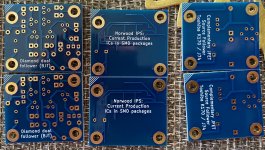
it's done
It took a little longer to write the descriptions.
I hope my English is good enough for the descriptions to be understandable.
If you have any questions, I will answer them, of course
first the minimal configuration:
PCU -> Preamp – Control - Unit
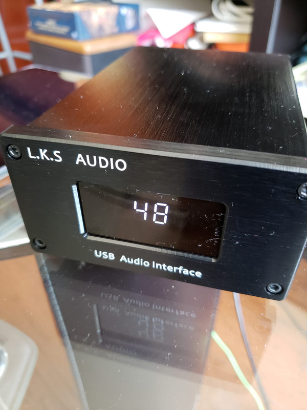
minimal configuration (Main board, Display OLED or LCD)
with the minimal configuration
(without the pcb for multiple input channels)
the following functions are available:
-volume
-balance
-gain (for values bigger than 0 the pcu works as an preamp)
also all standard functions like:
the real-time clock
startup volume configuration
remote control as well as controlling with rotary encoders.
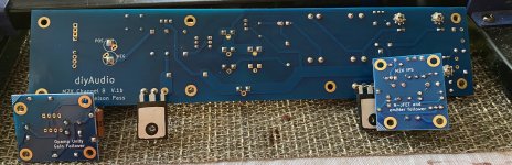
and here now the complete PCU with all possibilities
Preamp - Control - Unit
the pcu is a modular expandable preamp-controller unit,
working with the muses72320 audio chip.
all functions and sectors of the pcu, as well as the digital and analog sections are separated across different pcbs, to avoid unwanted noise in the audio signal path from the digital section. the pcu can also work as a preamp itself, according to the digital selectable gain value. because of the modular design, many different expansion states and configurations are possible. going from a simple volume regulation up to full functionality including phono-preamp (mm/mc), subwoofer control unit, different input channels, oled display, smartphone as remote control over bluetooth and an ir-remote (learnable). furthermore you can select different grades of operational amplifiers for the preamp functionality, which can also be swapped at any later time. an upgrade is always possible, so that you are also able to use future hardware developments and connect them simply to the pcu. extra functionalities can also be unlocked with a new software. the power supply is handled by specially designed low noise power supplies. you have the possibility to install software updates on the processors, to always get the latest fixes and new functionalities/options.
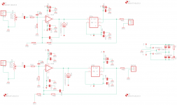
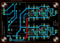
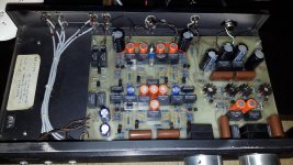
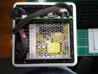
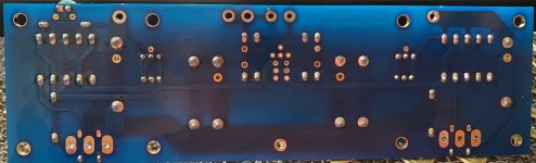
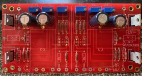
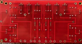
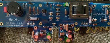
Main-Board:
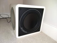
digital and analog section are completely isolated. high quality parts used in the audio signal path, to prevent signal distortion. muses72320 chip for volume, balance and gain control. muses01 operational amplifier (highest opamp configuration) with digitally configurable gain for the preamp. software can detect, if an audio signal is present (i.e. to control the standby of external devices, threshold adjustable). emi filter in the audio and power signal paths against noise in the frequency range of cellphones or wlan. high quality smb-connectors for lossless signal transmission. all extension boards share the same connector to connect them to the main-board. because of this a confusion of the connectors is not possible. a security mechanism exists, to prevent damage from wrong connected boards; no electrical damage can occur. updates can be installed with an optional usb-software-updater and included software for mac or pc. every input channel can be given a custom name, an offset of the volume and gain adjust is also available separately for each input channel, to hold every channel at the same base volume and select different preamp values. the time, how long a channel is active, is saved (i.e. to monitor the playtime of phono cartridges). when switching to another input channel, the volume gets faded down first, the input signal get galvanic isolated (mute), only now the actual channel is switched and the volume fades back up. the startup volume is adjustable (or use the previous volume from last power on). subwoofer: an extension board to control a subwoofer is available. the cutoff frequency and phase (including graphical rendering of the functions) for the subwoofer signal can be digitally adjusted. however,
no digital parts are used in the signal path.
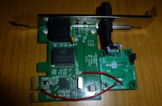
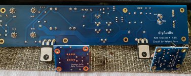
digital section: automatic detection, which extension boards are connected and which configuration is present, without manual adjustment. this enables easy plug and play. monitoring of all critical components and extension boards to show the user a warning if incorrect wiring or defect components are present. setting current time and date, real time clock chip included. the clock will pre preserved during power down. status and error display using seven segment display and leds. monitoring of all voltages in the system, over and under voltage protection. monitoring of the current in the system. if an over or under voltage case is detected, the protection circuit will shut off every component to prevent electrical damage. polarity protection, temperature protection and monitoring. every board can be shut off separately and the digital sections can be put into a deep sleep mode to enable standby functionality. if connections for the power supply are missing, the user will get an according error message and all components and extension boards will not be started to prevent electrical damage.
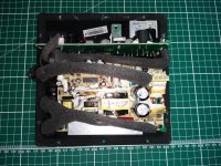
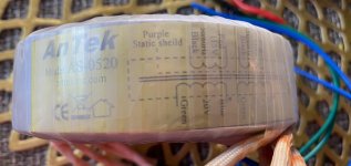
now I make the descriptions for the power supplys
+/- 15 V (PCU)
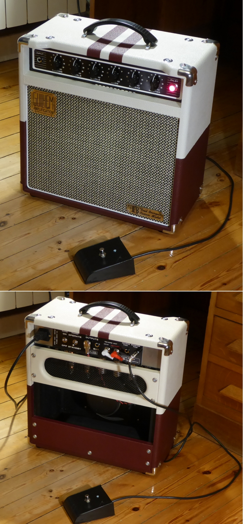
24 V (Nutube)


