I've been playing around with a few ideas for the power supply in my SET tube amp.
Specifically thinking about using a resistor input layout. I found one thread on the subject on the forums, but there wasn't really much info in it. I couldn't find much else online either.
I understand that introducing additional resistance into the B+ rail will drop voltage and create heat, also that if I were dealing with something other than a fully class A amp, the regulation of the power supply would be worse..
But for my application where I'm running with a constant current, and can deal with (and would actually prefer the lower voltage), other than creating heat in the resistor(s) prior to the first cap, I don't really see any downsides.. Am I missing anything with this thought process.
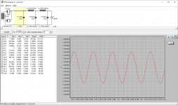
I've attached a couple PSUD2 sims, same power supply, except that one has resistance before the first cap. To me it looks like RMS current draw from the transformer is reduced fairly significantly, current spike when powering up is nearly halved, rectifier peak voltage is reduced, RMS current through the chokes and over caps is reduced, and ripple stays basically the same.
It seems to me that the pros outweigh the cons in my particular use case scenario. I just wanted to see what others thought about this idea though, and see if anyone has done this before and can comment on it.
Specifically thinking about using a resistor input layout. I found one thread on the subject on the forums, but there wasn't really much info in it. I couldn't find much else online either.
I understand that introducing additional resistance into the B+ rail will drop voltage and create heat, also that if I were dealing with something other than a fully class A amp, the regulation of the power supply would be worse..
But for my application where I'm running with a constant current, and can deal with (and would actually prefer the lower voltage), other than creating heat in the resistor(s) prior to the first cap, I don't really see any downsides.. Am I missing anything with this thought process.
I've attached a couple PSUD2 sims, same power supply, except that one has resistance before the first cap. To me it looks like RMS current draw from the transformer is reduced fairly significantly, current spike when powering up is nearly halved, rectifier peak voltage is reduced, RMS current through the chokes and over caps is reduced, and ripple stays basically the same.
It seems to me that the pros outweigh the cons in my particular use case scenario. I just wanted to see what others thought about this idea though, and see if anyone has done this before and can comment on it.
Attachments

Based on the simulations it seems like there are potentially some benefits given the right circumstances.. I'm just wondering if this is a case of PSUD2 not correctly simulating this scenario, or if for most cases the cons outweigh the pros.
Based on the simulations it seems like there are potentially some benefits given the right circumstances.. I'm just wondering if this is a case of PSUD2 not correctly simulating this scenario, or if for most cases the cons outweigh the pros.
What you are doing is nothing more than using a different rectifier with higher voltage drop. Of course if you need more drop than any other rectifier can give then you have to add more R, or use a different PT, or you can also add R in each AC leg ahead of the rectifier.
Last edited:
What you are doing is nothing more than using a different rectifier with higher voltage drop. Of course if you need more drop than any other rectifier can give then you have to add more R, or use a different PT, or you can also add R in each AC leg ahead of the rectifier.
Yeah okay that makes sense, but the reduced RMS current load on the power transformer seems like a nice benefit of doing this.
Yeah okay that makes sense, but the reduced RMS current load on the power transformer seems like a nice benefit of doing this.
You don't just throw a resistor into the PS because you feel like it will reduce the strain in the PT. You have to design the amp first and then give those circuits what they require for voltage and current. If your PT sends higher B+ to amp than your design calls for then you have to drop that voltage somehow. But in the end you have to give all the branches of the amp what they need as designed. The amp circuit dictates everything and the PS is built to accomodate that.
You don't just throw a resistor into the PS because you feel like it will reduce the strain in the PT. You have to design the amp first and then give those circuits what they require for voltage and current. If your PT sends higher B+ to amp than your design calls for then you have to drop that voltage somehow. But in the end you have to give all the branches of the amp what they need as designed. The amp circuit dictates everything and the PS is built to accomodate that.
Who said I want to throw a resistor into the PS because I feel like it? I am trying to determine if doing this will have the effect that PSUD2 seems to indicate it will, and if so - has anyone had experience doing this specifically.
The amp is already designed, and it can operate anywhere between 900VDC and 1250VDC, it's using a fixed bias power stage which I can adjust accordingly. The power transformer runs a bit hot, and though it's rated for the current I'm currently using I am trying to figure out if maybe I could reduce strain on some of the components by implementing this.
Why can't this be a discussion about the effect of adding additional resistance before the first C in a power supply?
If you want to trim down the voltage, I would pop open the Hammond choke page and start simulating a variety of chokes in place of the resistor you have there. Pay careful attention to the choke current though, as it will be more than your DC current draw, so the choke will need some operating headroom.
Doing this will drop the power transformer current even more and should knock the ripple down too (not that you need it based on your sims).
The big problem with using that resistor is that you'd want a 60+ watt rated part to dissipate all the heat that thing is going to generate!
Doing this will drop the power transformer current even more and should knock the ripple down too (not that you need it based on your sims).
The big problem with using that resistor is that you'd want a 60+ watt rated part to dissipate all the heat that thing is going to generate!
If you want to trim down the voltage, I would pop open the Hammond choke page and start simulating a variety of chokes in place of the resistor you have there. Pay careful attention to the choke current though, as it will be more than your DC current draw, so the choke will need some operating headroom.
Doing this will drop the power transformer current even more and should knock the ripple down too (not that you need it based on your sims).
The big problem with using that resistor is that you'd want a 60+ watt rated part to dissipate all the heat that thing is going to generate!
The other thread that I found on this subject went down the same path, everyone was suggesting using a choke input design. For the purposes of at least examining the use of a resistor in this position though, I'd like to look at the pros and cons. There seem to be at least some pros, and I would like to see if those make sense for me.
I think that using 200 ohms of resistance in this position would consume 10.1W of power. I had thought that using 2 x 100 ohm 20W resistors might be suitable for this if I did try it out.
I use a resistor input power supply on my preamp. I originally designed it for a 5R4 and used the single resistor after the rectifier instead of two plate resistors to limit the inrush current. It turned out that the voltage was too low, but just right when I used a 5V4 instead, so I just kept the resistor. I also noticed the significantly lower transformer current when I modeled it in PSUD.
Your simulation shows 318mA of RMS current. That is 20W of dissipation. If you use two 20W 100 ohm resistors, they will probably last 2-3 years (assuming you aren't using the aluminum heatink type, which won't last even that long).
Your simulation shows 318mA of RMS current. That is 20W of dissipation. If you use two 20W 100 ohm resistors, they will probably last 2-3 years (assuming you aren't using the aluminum heatink type, which won't last even that long).
Oh, you're right. I was looking at the RMS current from the power transformer. I was looking at some Ohmite brown devils, but yeah I'm not happy with where 10W per resistor would put them. Thanks for pointing that out. Perhaps a pair of these https://www.vishay.com/docs/31838/fvt.pdf in the 50W variant would be a better choice.
I use a resistor input power supply on my preamp. I originally designed it for a 5R4 and used the single resistor after the rectifier instead of two plate resistors to limit the inrush current. It turned out that the voltage was too low, but just right when I used a 5V4 instead, so I just kept the resistor. I also noticed the significantly lower transformer current when I modeled it in PSUD.
Thanks for the feedback.
Yes, a pair of those 50W tubular resistors would be a good choice. They are absolutely gigantic (I have used the 3K/50W ones a few times recently) and not all that inexpensive.
So yes, you can do this with resistors. It will produce a lot of extra heat in the chassis, take up a lot of extra space, and not quite perform as well as a choke would, but it's doable.
So yes, you can do this with resistors. It will produce a lot of extra heat in the chassis, take up a lot of extra space, and not quite perform as well as a choke would, but it's doable.
Yes, a pair of those 50W tubular resistors would be a good choice. They are absolutely gigantic (I have used the 3K/50W ones a few times recently) and not all that inexpensive.
So yes, you can do this with resistors. It will produce a lot of extra heat in the chassis, take up a lot of extra space, and not quite perform as well as a choke would, but it's doable.
Hm.. So the question that I need to consider then, is whether the extra space and heat of these resistors is worth it for the reduction in RMS current through the power transformer & rectifier.
I could also use 2 x 50 ohm resistors, which would put the power consumption of each resistor at 5W, likely making the 20W brown devil's suitable.. Though the reduction in RMS current is not as significant.
If I were to use a choke input, I'd need a different power transformer as it would put my B+ too low. Though I was looking at the Sowter choke-input chokes, and they do look like a nice option. I wanted to look at options other than replacing power transformer though.
You don't need to use a special choke for what you're doing.
Try the simulation with a Hammond 158TA, which is 1.5H/40 ohms and rated for 300mA of current. Note the output voltage and the RMS current across the choke itself to see how well it will work for your situation.
Try the simulation with a Hammond 158TA, which is 1.5H/40 ohms and rated for 300mA of current. Note the output voltage and the RMS current across the choke itself to see how well it will work for your situation.
You don't need to use a special choke for what you're doing.
Try the simulation with a Hammond 158TA, which is 1.5H/40 ohms and rated for 300mA of current. Note the output voltage and the RMS current across the choke itself to see how well it will work for your situation.
I did notice those, in fact there's even a 1.5H/27 ohm one rated for 500mA, the 159V. It does seem as though this would be suitable for the 250mA RMS that I'm getting from PSUD2.
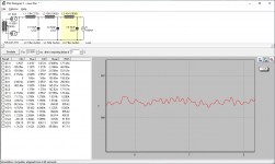
I just noticed though that the waveform of the output with a choke of this size seems to be really weird, once I get up to more like a 10H choke input though PSUD2 shows the waveform to be much more steady.
I had wondered if the lower Henry choke used as a choke input was an issue, or if this is just PSUD2 not plotting it correctly, or maybe correctly but it's not an issue that the waveform looks odd.
Also, this strange waveform makes it difficult to estimate the amount of ripple this power supply would have.. It kind of seems like it would be a lot, which would potentially mean more downstream filtering..
Attachments
Last edited:
That waveform is a little odd. Try making C1 52uF.
Notice that your power transformer current has dropped to well below 200mA? RMS choke current is 250mA, so you could try going up in inductance slightly with a slightly lower current rating to see how things go.
Notice that your power transformer current has dropped to well below 200mA? RMS choke current is 250mA, so you could try going up in inductance slightly with a slightly lower current rating to see how things go.
That waveform is a little odd. Try making C1 52uF.
Notice that your power transformer current has dropped to well below 200mA? RMS choke current is 250mA, so you could try going up in inductance slightly with a slightly lower current rating to see how things go.
Same weirdness.. Though if I put a small 0.1uF cap before that first choke the current draw from the power transformer stays quite low, but does seems to bring it back to a normal waveform.. So I guess that's an option.
Though because this is in such a high voltage rail, I'm worried those Hammond chokes wouldn't be up to that task.. It says maximum operating voltage for the 159V is 500VDC, though they're hipot tested to 1500VAC.
Last edited:
Instead of a resistor you could maybe use one or two incandescent light bulbs... you can't have too many bottles amirite?
Instead of a resistor you could maybe use one or two incandescent light bulbs... you can't have too many bottles amirite?
I appreciate the help! Is this from a chapter in your tube hi-fi book?
- Home
- Amplifiers
- Tubes / Valves
- Resistor input power supply